Combustion liner with enhanced heat transfer

a combustion liner and heat transfer technology, applied in the direction of machines/engines, mechanical equipment, lighting and heating apparatus, etc., can solve the problems of not providing a uniform heat transfer improvement across all coated surfaces, not enough material selection alone to maintain component life in the harsh combustion environment, etc., to achieve enhanced heat transfer capabilities, increase the surface area of the liner wall, and improve heat transfer

Active Publication Date: 2008-06-17
H2 IP UK LTD
View PDF27 Cites 29 Cited by
  • Summary
  • Abstract
  • Description
  • Claims
  • Application Information

AI Technical Summary

Benefits of technology

[0007]A combustion liner for a gas turbine combustor is disclosed having enhanced heat transfer capabilities. The combustion liner comprises a first end, a second end, a generally annular wall about a centerline, with the annular wall having an inner surface and an outer surface. Fixed to the liner outer surface is a plurality of attachment points for fixing the liner within the combustor. A region of the liner outer surface from proximate the first end to proximate the attachment points is textured in a substantially uniform pattern. This uniform pattern preferably comprises a plurality of intersecting grooves formed in the liner outer surface, which increases the liner wall surface area, and for a given amount of cooling fluid passing over the liner outer surface, heat transfer is improved. Various embodiments are disclosed with respect to the substantially uniform pattern and cooling fluid passing over the liner outer surface.

Problems solved by technology

However, material selection alone is not sufficient to maintain component life in the harsh combustion environment.
While this type of heat transfer augmentation is an improvement, it does not necessarily provide a uniform heat transfer improvement across all coated surfaces nor is a coating type heat transfer augmentation device preferable around cooling holes due to the processing requirements necessary to maintain open cooling holes and properly sized cooling holes.

Method used


Image

  • Combustion liner with enhanced heat transfer
  • Combustion liner with enhanced heat transfer
  • Combustion liner with enhanced heat transfer

Examples


Embodiment Construction

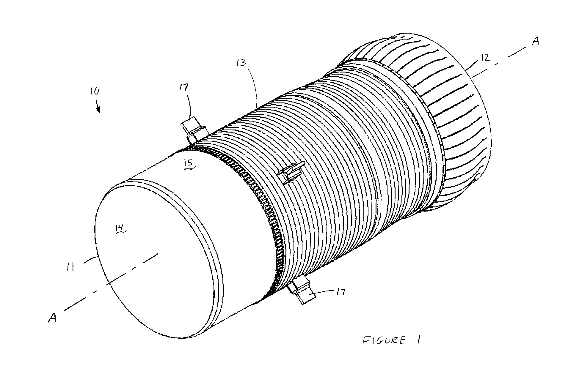
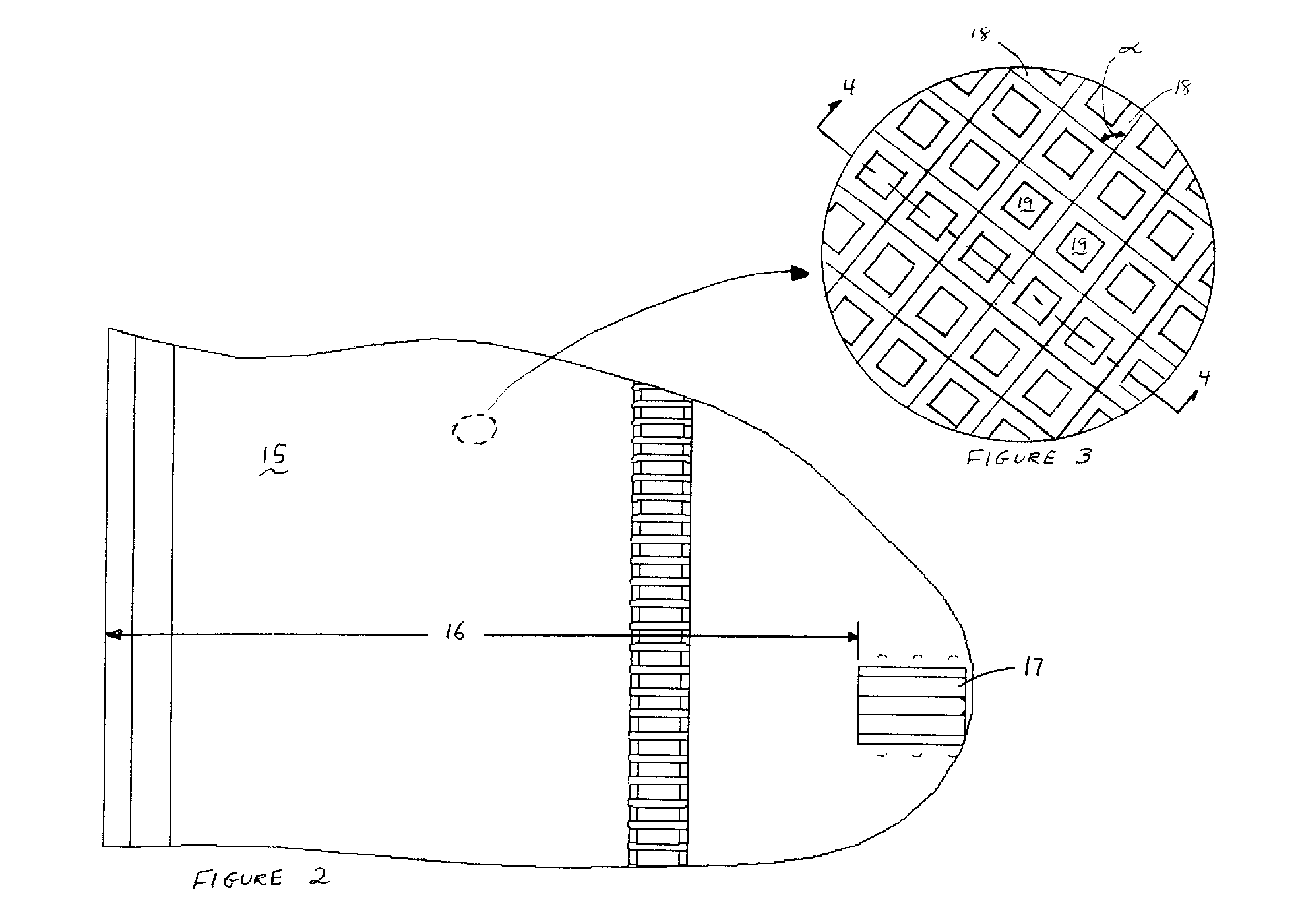
[0013]The present invention will now be described in detail with reference to FIGS. 1-4B. Referring now to FIG. 1, a combustion liner 10 is shown in perspective view having enhanced heat transfer capabilities. Combustion liner 10 comprises first end 11, second end 12, and generally annular wall 13 about centerline A-A. Generally annular wall 13 further comprises inner surface 14, outer surface 15, and a thickness therebetween. Fixed to outer surface 15 at a first distance 16 from first end 11 is a plurality of liner stops 17. The positioning of the liner stops 17 is more clearly shown in FIG. 2. As one skilled in the art understands, liner stops 17 are distinct bracket-like components that serve as attachment points for securing the combustion liner 10 within a mating component of a combustor. As it can be seen from FIGS. 1 and 2, the plurality of liner stops 17 extend radially outward from the outer surface 15 and have a length and width that extend along the outer surface 15. To f...


PUM


Abstract

A combustion liner having enhanced heat transfer over at least a portion of the liner is disclosed. The combustion liner comprises, amongst other features, an outer surface wherein at least a region of the outer surface is textured in a substantially uniform pattern such that the surface area exposed to a passing cooling medium is increased, thereby increasing the heat transfer through the combustion liner. Multiple embodiments of textured patterns are also disclosed.

Description

BACKGROUND OF THE INVENTION[0001]The present invention relates generally to gas turbine combustion liners and more specifically to a manner in which to improve the heat transfer through the combustion liner.[0002]Gas turbine engines are a well-established form of technology capable of mechanical output in the form of propulsive thrust or shaft power for electrical generation. Gas turbine engines are well known in aircraft and power generation applications. A typical gas turbine engine comprises at least a compressor, a combustion system, and a turbine, which is coupled to the compressor. Depending on the power output required, the combustion system can comprise a single combustor or a plurality of combustors.[0003]Within a gas turbine combustor, fuel is mixed with compressed air and introduced to an ignition source upon which combustion occurs, producing hot combustion gases that are directed to drive the turbine. This reaction of the fuel and compressed air mixture typically occurs...

Claims


Application Information

Patent Timeline
Patent Type & Authority Patents(United States)
IPC IPC(8): F02C1/00F02G3/00
CPCF23R3/005F23R3/42Y02T50/675Y02T50/60
Inventor GREEN, ANDREWSTUTTAFORD, PETERCARELLA, JOHNDURAIBABU, VAMSIJENNINGS, STEPHEN
Owner H2 IP UK LTD
Why Eureka
Try Eureka