Large capacity multiple service floor box

a service floor box, large capacity technology, applied in the field of electric boxes, can solve the problems of liquids seeingping into the housing and past the cover, and achieve the effect of convenient assembly

Active Publication Date: 2008-06-17
HUBBELL INC
View PDF36 Cites 21 Cited by
  • Summary
  • Abstract
  • Description
  • Claims
  • Application Information

AI Technical Summary

Benefits of technology

[0006]Still another object of the invention is to provide an electrical box that is easily assembled.
[0007]A further object of the invention is to provide an electrical box that provides easy access to the wiring and other elements contained within the box.

Problems solved by technology

Among other things, a recurring problem with floor mounted electrical boxes is seepage of liquids past the cover and into the housing.

Method used


Image

  • Large capacity multiple service floor box
  • Large capacity multiple service floor box
  • Large capacity multiple service floor box

Examples


Embodiment Construction

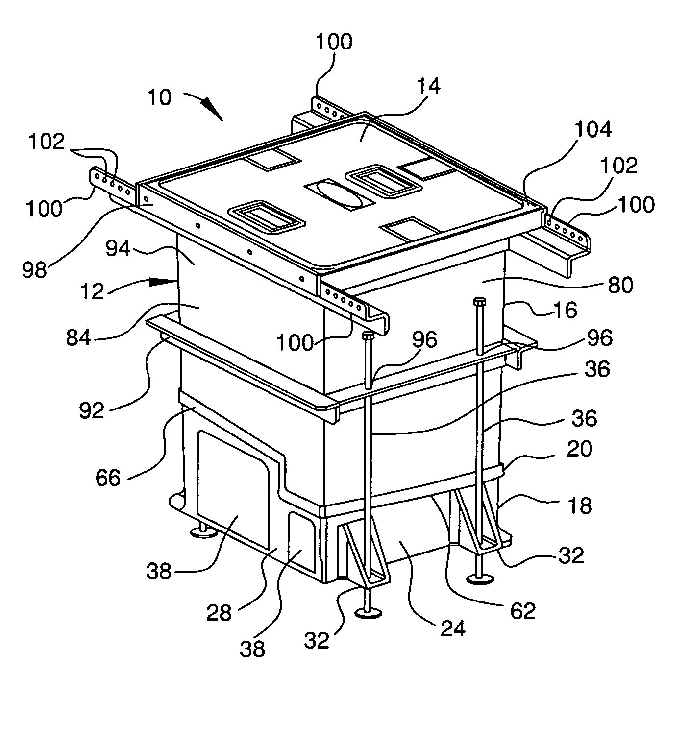
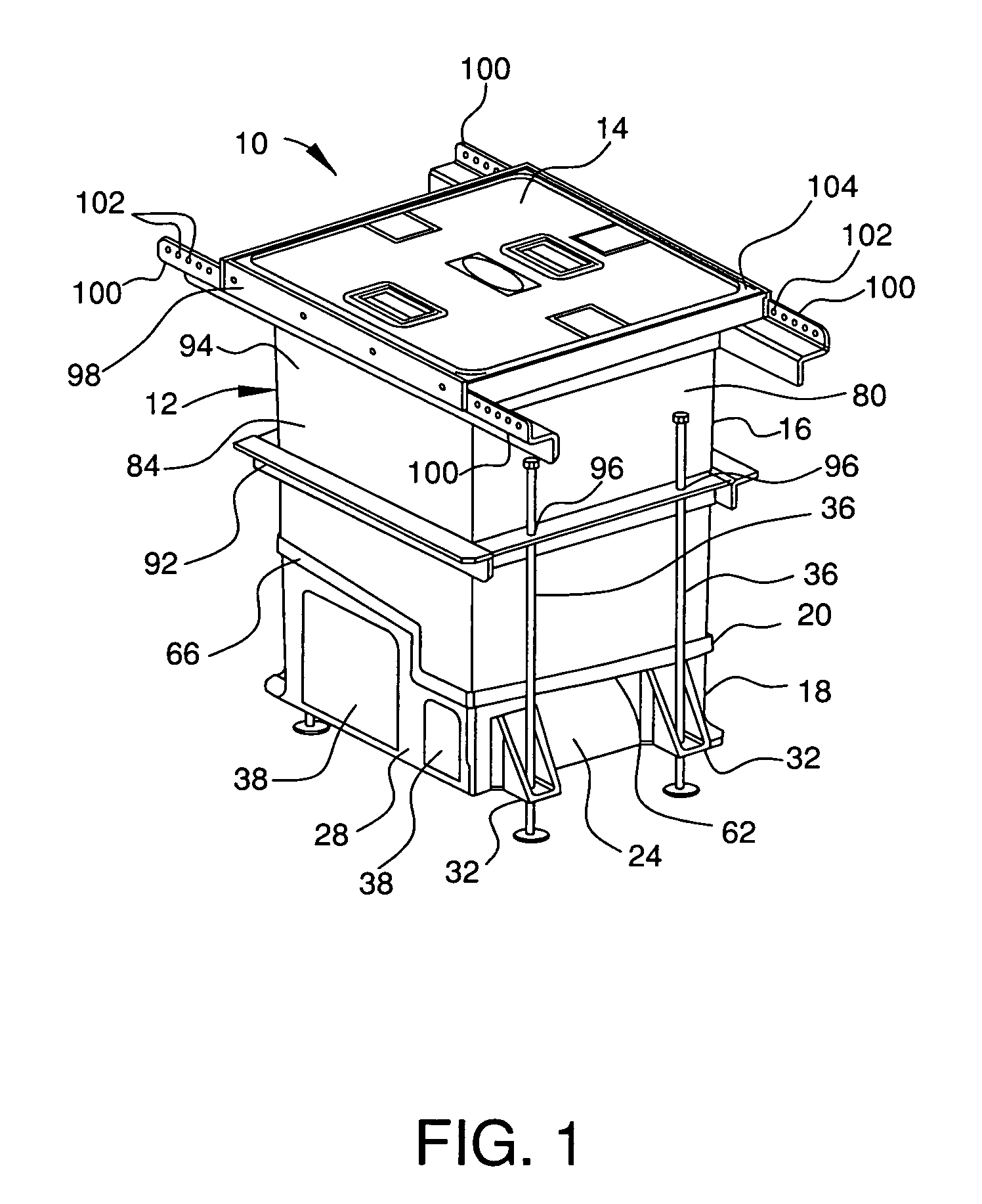
[0024]Referring initially to FIGS. 1 and 2, the electrical floor box 10 in accordance with the invention has a housing 12 with a cover 14. The floor box provides multiple services (power and low voltage) and is particularly suitable for use in convention centers. Preferably, the housing has an interior dimension of approximately 18 inches square and 24 inches deep. The electrical floor box is installed in a concrete floor by placing the box into position and then pouring concrete around the box.

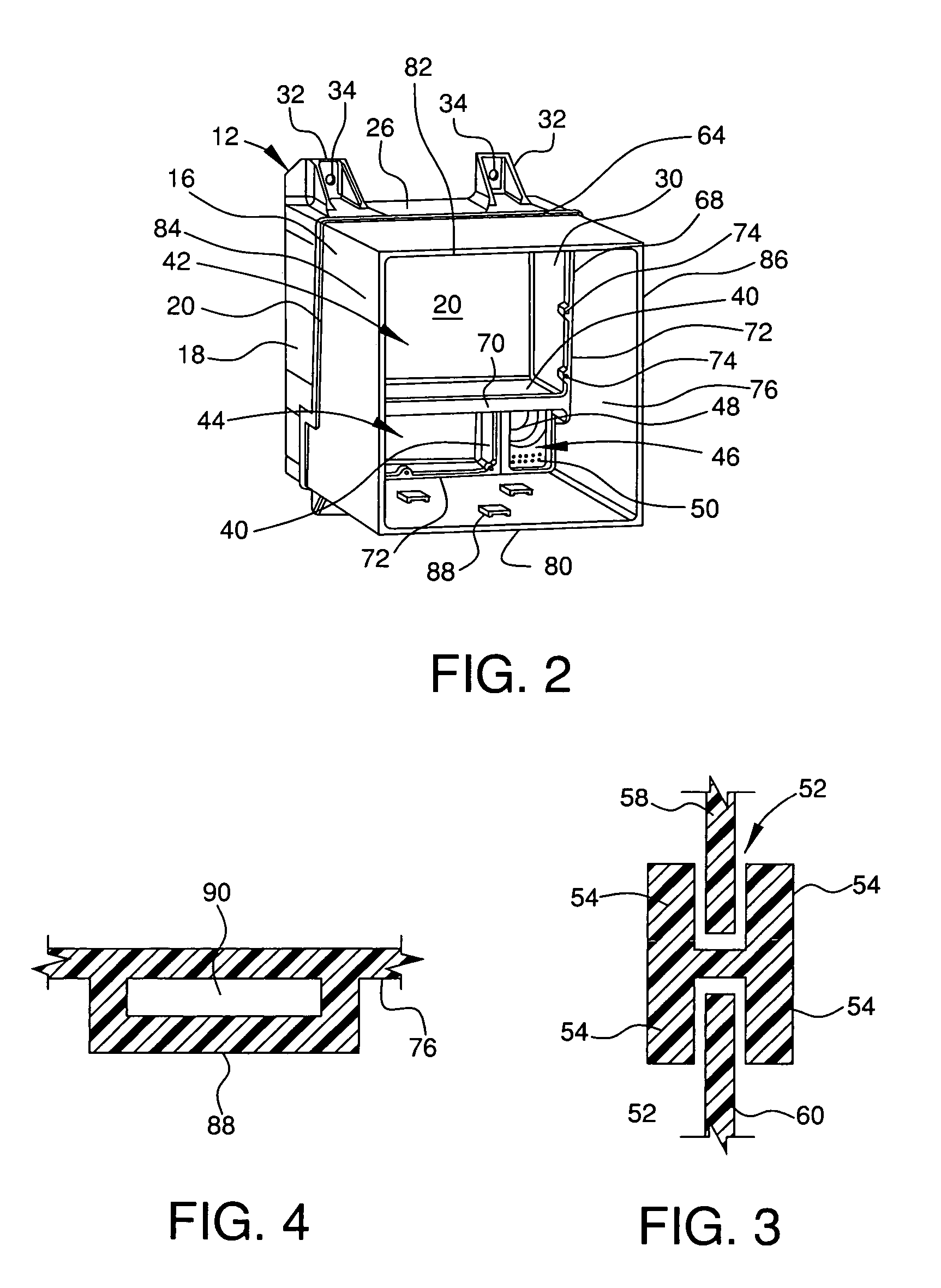
[0025]The housing 12 has three sections: a top section 16, a bottom section 18, and a connecting, middle section 20. Each of the three sections is preferably formed by reaction injection molding a polyurethane material. The bottom section 18 of the power housing 12 has a floor 22, a front sidewall 24, a rear sidewall 26, a left sidewall 26, and a right sidewall 28. The front sidewall 24 and rear sidewall 26 both have two integral feet 32 with holes 34 therein to allow threaded leveling rods 3...


PUM


Abstract

An electrical floor box for providing multiple services such as electrical service and communication service has a housing formed from a top section, a bottom section, and a middle section connecting the top and bottom section. The housing is covered by a cover that rests in a cover flange. The cover flange has a gutter for collecting any liquids that seep into the housing. A removable power panel rests in the interior of the housing and provides electrical receptacles. An accessory box for providing additional services such as compressed air and water can be attached to electrical floor box.

Description

FIELD OF THE INVENTION[0001]The present invention generally relates to electrical boxes. More specifically, the present invention relates to an electrical box for mounting in a concrete floor.BACKGROUND OF THE INVENTION[0002]Electrical boxes are installed in concrete floors to provide outlets for various services, such as electrical power service or lower voltage service for telephone and data communications. Typical floor boxes have a housing with a removable cover to allow access to the interior of the housing. Among other things, a recurring problem with floor mounted electrical boxes is seepage of liquids past the cover and into the housing. This occurs because concrete floors in places such as convention centers are often hosed off to clean the floors.[0003]Thus, there is a continuing need to provide electrical boxes which prevent seepage of liquid into the interior compartment of the housing. Additionally, there is a continuing need to provide electrical boxes that are easily ...

Claims


Application Information

Patent Timeline
Patent Type & Authority Patents(United States)
IPC IPC(8): H02G3/08
CPCH02G3/185H02G9/10
Inventor SCANZILLO, THOMAS L.
Owner HUBBELL INC
Why Eureka
Try Eureka