
Image stitching for a multi-head printer

Inactive Publication Date: 2008-06-17
ZINK IMAGING
View PDF20 Cites 32 Cited by
  • Summary
  • Abstract
  • Description
  • Claims
  • Application Information

AI Technical Summary

Benefits of technology

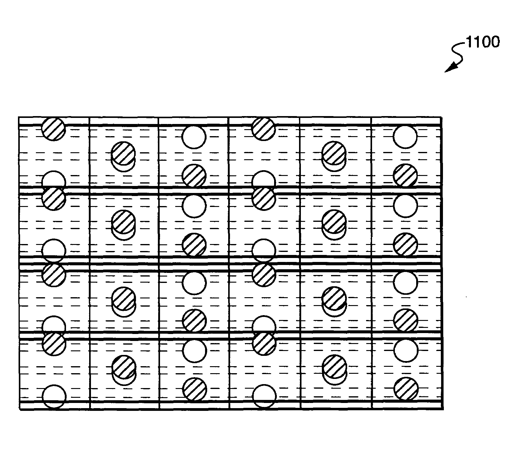
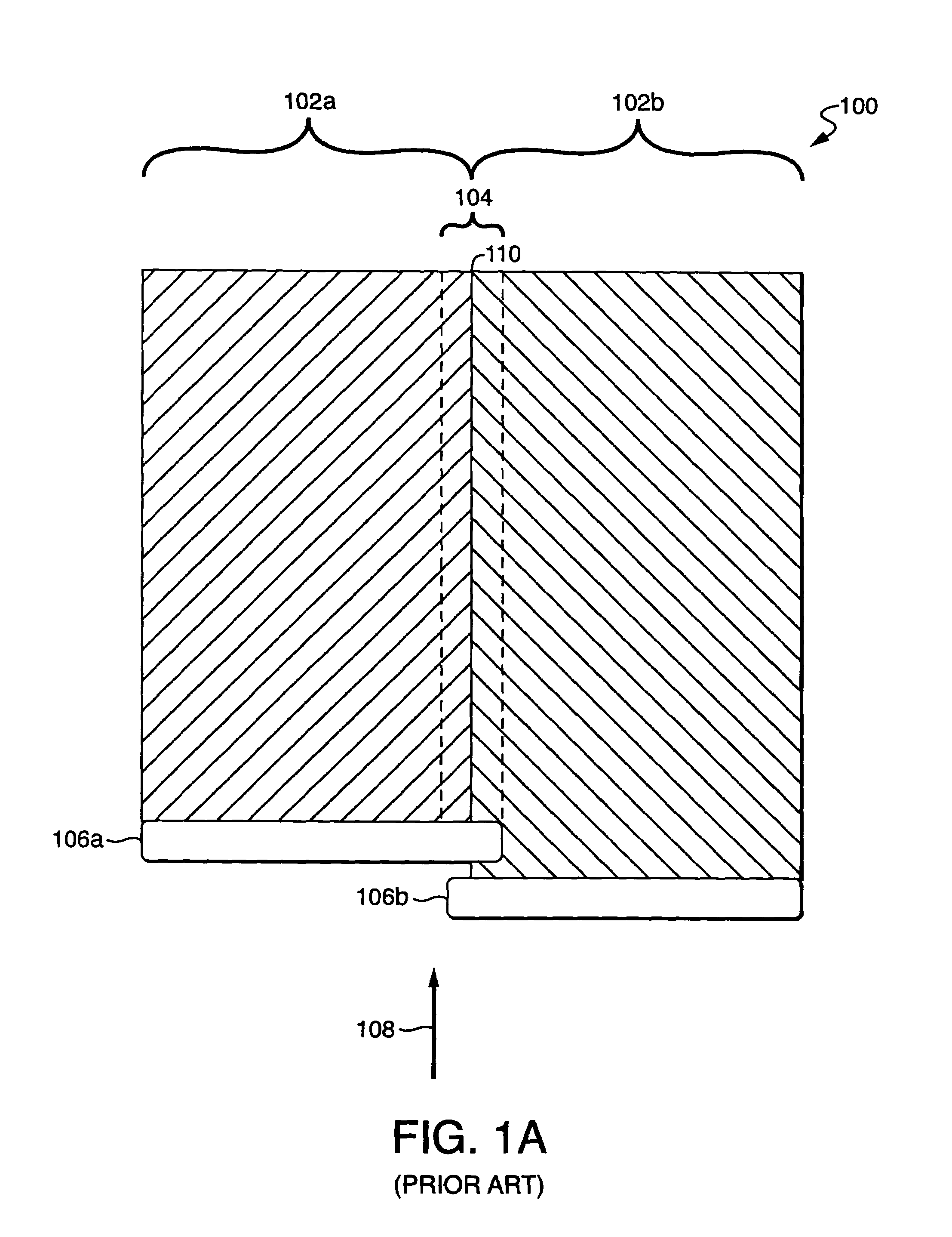
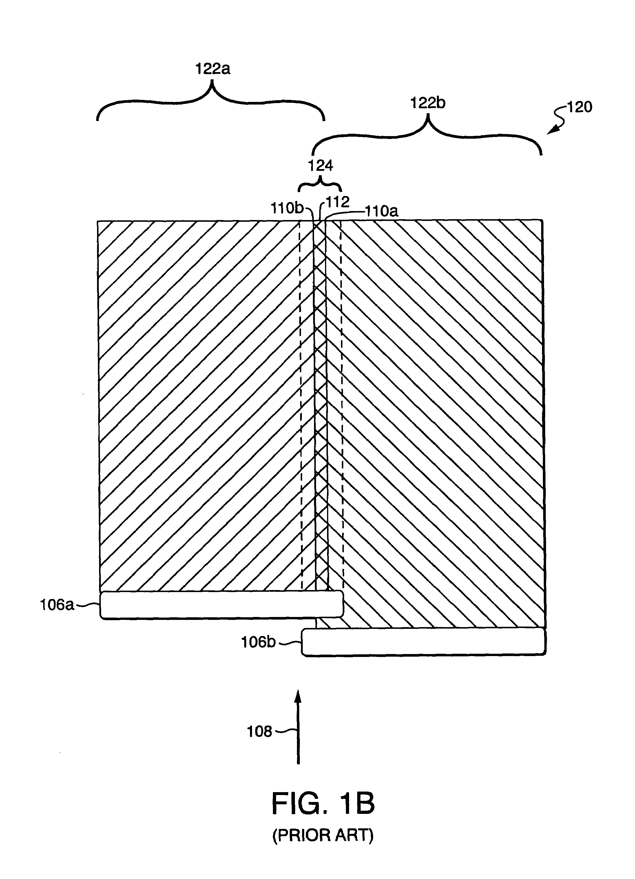
[0011]Techniques are disclosed for stitching images printed by a multi-head printer in a manner that is relatively insensitive to misregistration of the image segments. When a pair of overlapping print heads print a pair of adjacent image segments which meet in a stitching region, printing at each location in the stitching region is accomplished by both print heads with a weighting that depends on the location being printed within the stitching region. In one embodiment, for example, the output of each print head is weighted by a linear function of horizontal pixel position. Techniques are also disclosed for selecting screening patterns for use when stitching is performed with variable-dot printers. Such screening patterns are selected to minimize variations in density that may arise as the result of cross-web and / or down-web misregistration.

Problems solved by technology

This method of journey is troublesome, because it lacks robustness toward imperfections in the printer hardware.
For example, if the paper motion is not perfectly perpendicular to the print heads, then the paper may shift slightly to the right or left when traveling from one set of print heads to the other, thereby opening a gap in the stitch or causing an overlap of image segments.
In addition to these mechanical imperfections, the thermal print head heats up as it prints, and thermal expansion of the heads can cause a visible overlap of image segments.
This imperfection, however, extends the full length of the image, and may be visible despite its narrow width.
This avoids correlated defects that extend the full length of the image, but it does place demands on the mechanical and thermal tolerances of the printer, as a misregistration of the patterns will result in significant uncontrolled changes in the printed density of the stitch region.

Method used


Image

  • Image stitching for a multi-head printer
  • Image stitching for a multi-head printer
  • Image stitching for a multi-head printer

Examples


Embodiment Construction

[0032]Techniques are disclosed for stitching images printed by a multi-head printer in a manner that is relatively insensitive to misregistration of the image segments. When a pair of overlapping print heads print a pair of adjacent image segments which meet in a stitching region, printing at each location in the stitching region is accomplished by both print heads with a weighting that depends on the location being printed within the stitching region. In one embodiment, for example, the output of each print head is weighted by a linear function of horizontal pixel position. Techniques are also disclosed for selecting screening patterns for use when stitching is performed with variable-dot printers. Such screening patterns are selected to minimize variations in density that may arise as the result of cross-web and / or down-web misregistration.

[0033]In various embodiments of the present invention, techniques are provided for use in a printer to stitch images in a manner that is relati...


PUM


Abstract

Techniques are disclosed for stitching images printed by a multi-head printer in a manner that is relatively insensitive to misregistration of the image segments. When a pair of overlapping print heads print a pair of adjacent image segments which meet in a stitching region, printing at each location in the stitching region is accomplished by both print heads with a weighting that depends on the location being printed within the stitching region. In one embodiment, for example, the output of each print head is weighted by a linear function of horizontal pixel position. Techniques are also disclosed for selecting screening patterns for use when stitching is performed with variable-dot printers. Such screening patterns are selected to minimize variations in density that may arise as the result of cross-web and / or down-web misregistration.

Description

BACKGROUND[0001]1. Field of the Invention[0002]The present invention relates to multi-head thermal printers and, in particular, to thermal printers in which multiple print heads are used to print a single image in the form of multiple joined segments.[0003]2. Related Art[0004]Various kinds of printers are well-known in the computing and digital image arts. Such printers include, for example dot-matrix printers, laser printers, inkjet printers and thermal printers. The focus of the present discussion is on thermal printers, so-named because they use thermal energy (heat) to produce printed output. More specifically, thermal printers typically contain a linear array of heating elements (also referred to herein as “print head elements”) that print on an output medium by, for example, transferring pigment from a donor sheet to the output medium or by initiating a color-forming reaction in the output medium. The output medium is typically a porous receiver receptive to the transferred pi...

Claims


Application Information

Patent Timeline
IPC IPC(8): G06K15/00G06F13/00B41J2/355B41J2/505H04N1/387
CPCB41J2/355B41J2/5056H04N1/3876
Inventor SAQUIB, SUHAIL S.VETTERLING, WILLIAM T.
Owner ZINK IMAGING
Learn More