Method and device for producing subsurface markings in a transparent material body

a technology of transparent materials and subsurface markings, which is applied in the direction of duplicating/marking methods, lasers, decorative arts, etc., can solve the problems of high production cost, high production cost, and poor quality of subsurface markings, and achieves fast operation, simple design, and reduced production cost.

Inactive Publication Date: 2008-06-17
VITRO LASER TECH AG
View PDF13 Cites 6 Cited by
  • Summary
  • Abstract
  • Description
  • Claims
  • Application Information

AI Technical Summary

Benefits of technology

[0006]It is therefore an object of the invention to provide a method for producing subsurface marking, where optical variations of the individual markings, particularly with respect to their size, can be easily realized, namely in a flawlessly reproducible fashion and with realistic optical properties. It is another object of the invention to provide a suitable device for this purpose.
[0015]The Q-switching makes it possible to change or modulate the optical quality (losses) of the laser resonator in such a way that a feedback and therefore a laser beam are only possible for short periods of time. The discharge pulse controls this Q-switch that may be realized in the form of an acousto-optical or electro-optical modulator or a generally active light switch.
[0017]Without the described Q-switching, the laser resonator would emit a laser pulse sequence that essentially follows the excitation pulse for realizing the population inversion in the laser material. However, the Q-switch or Pockels cell respectively makes it possible to generate laser monopulses with a pulse energy that is defined by the time delay on the output side. The duration of the corresponding discharge pulse simultaneously controls the duration of the resulting laser monopulse.
[0020]Consequently, the optical appearance of the entire internal engraving composed of the individual permanent markings also varies. Depending on the size of a bubble, the corresponding spot appears more or less bright when the transparent material body is penetrated by or exposed to the radiation of a white light source. In this context, the term “transparent” refers to the material body usually but not exclusively appearing translucent to the human eye, i.e., it is translucent in the visible range. Naturally, the scope of the invention also includes variations, in which the respective material body is only rendered translucent with auxiliary means. An infrared camera could conceivably be utilized for this purpose. However, transparent usually means that electromagnetic radiation in the range between approximately 400 nm-800 nm, i.e., in the visible range, is able to pass without practically any losses.
[0024]In addition, the method and the device allow for an extremely fast operation because no mechanical adjustments are carried out. This lowers the costs of a thusly manufactured material body. In addition, a functional impairment due to changes in the optical properties of the optical unit can be eliminated because the beam path does not change from laser pulse to laser pulse—namely even if the pulse energy varies.
[0025]The solid-state laser or laser as such can also be operated continuously. The output actually is controlled by the time delay between the excitation pulse and the discharge pulse only. Consequently, it is possible to reach maximum pulse energies when the time delay between the excitation pulse and the discharge pulse is zero. The pulse energy can be easily lowered from this maximum pulse energy to values that clearly lie below the destruction threshold of the material body. Due to this measure, it is not required to provide additional mechanical shutters or to take other measures for preventing unwanted markings. This additionally lowers the constructive expenditure and results in an extended service life as well as stable thermal and optical properties. These are the significant advantages of the invention.

Problems solved by technology

However, this method is associated with a significant constructive expenditure.
In addition, the precision in producing the markings and the quality of their appearance leave much to be desired.

Method used


Image

  • Method and device for producing subsurface markings in a transparent material body
  • Method and device for producing subsurface markings in a transparent material body
  • Method and device for producing subsurface markings in a transparent material body

Examples


Embodiment Construction

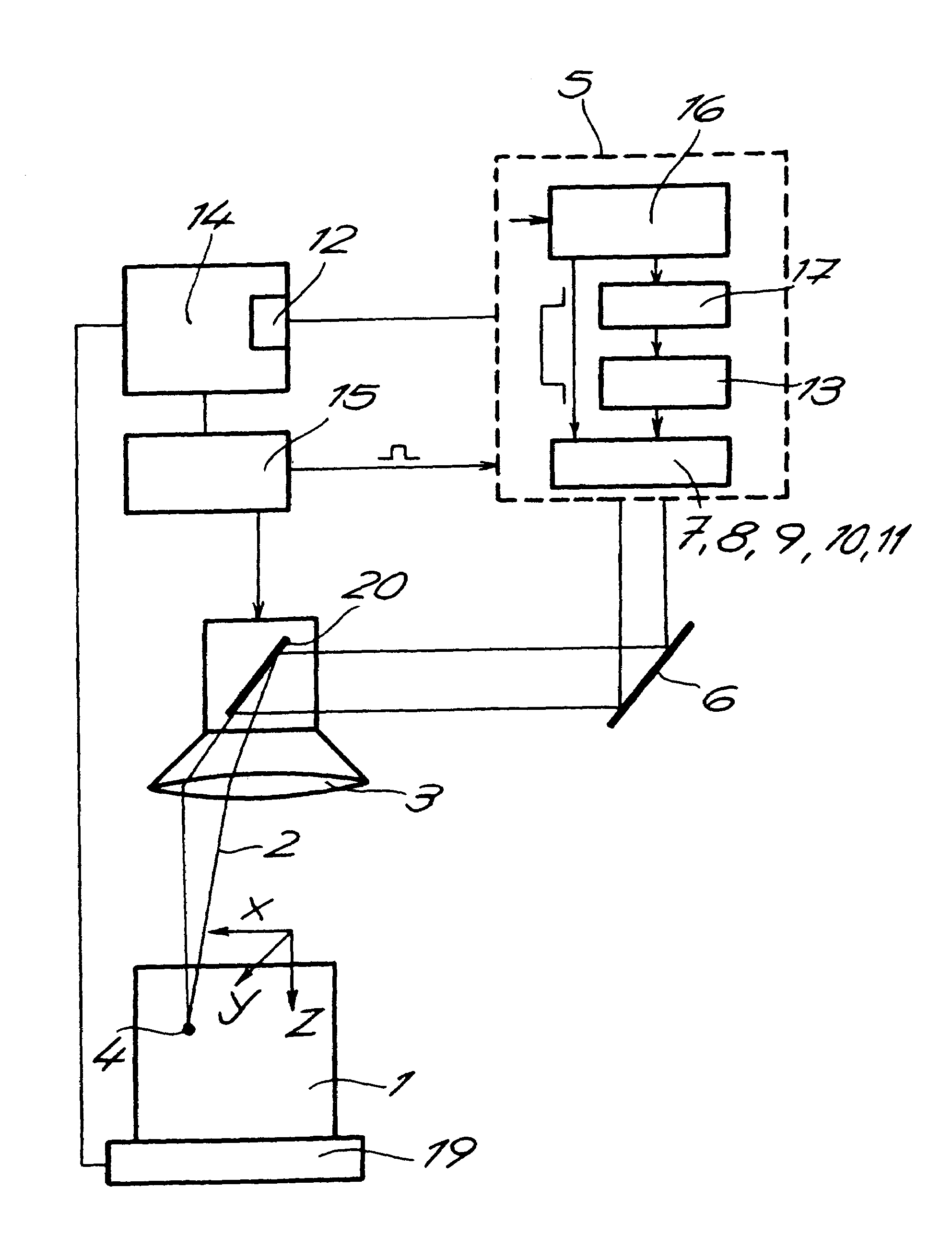
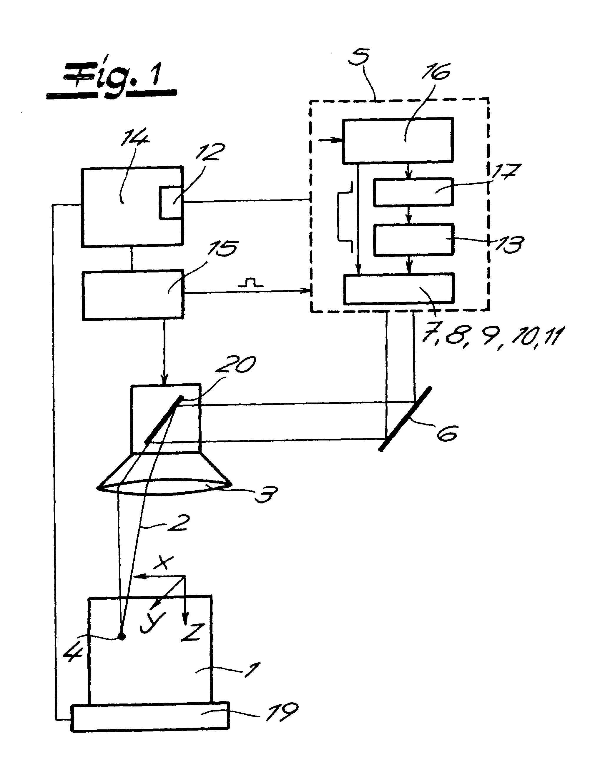
[0033]Referring now in detail to the drawings, there is shown a device for producing or inscribing subsurface markings in a transparent material body 1. This is achieved by focusing a pulsed laser beam 2 in the interior of material body 1 with the aid of an optical unit 3, 20 in such a way that pulsed laser beam 2 exceeds the destruction threshold of material body 1 at least in the respective focal point and a permanent marking 4 is produced. Localized fusion of the material with crack formation, which usually is macroscopically visible from outside in the form of “bubbles,” takes place due to the interaction between pulsed laser beam 2 and the material of material body 1 in the region of the respective focal point or, in general terms, in the region of a corresponding beam waist.

[0034]The respective marking 4 produced in material body 1 consists of a spherical inhomogeneity or bubble. In this case, radius r of a corresponding bubble or marking 4 (see FIG. 3) depends on the pulse en...


PUM

PropertyMeasurementUnit
diameteraaaaaaaaaa
diameteraaaaaaaaaa
wavelengthaaaaaaaaaa

Abstract

A method and device for producing subsurface markings in a transparent material body by focusing a pulsed laser beam in the interior of the material body so that the laser beam exceeds the destruction threshold of the material body to produce a permanent marking. Individual markings form a freely selectable internal engraving as a result of a relative movement between the laser beam and the material body. The laser pulse is varied with respect to its pulse energy (P) by means of a discharge pulse (E) that has an adjustable time delay from an excitation pulse (A). Markings that have varying optical properties depending on the pulse energy (P) are produced in this fashion.

Description

BACKGROUND OF THE INVENTION[0001]1. Field of the Invention[0002]The invention pertains to a method for producing subsurface markings in a transparent material body, wherein a pulsed laser beam is focused in the interior of the material body in such a way that the laser beam exceeds the destruction threshold of the material body at least in the respective focal point and a permanent marking is produced. Individual markings form a freely selectable internal engraving as a result of a relative movement between the laser beam and the material body.[0003]2. The Prior Art[0004]Methods of this type are generally known, for example, from U.S. Pat. No. 4,467,172 or German Patent No. DD 237 972 A3. U.S. Pat. No. 5,637,244 also pertains to such laser-based methods for producing an internal engraving in a material body. This material body may consist of glass such that an internal glass engraving is produced in this case. Naturally, it would also be possible to utilize plastic materials, e.g., ...

Claims


Application Information

Patent Timeline
Patent Type & Authority Patents(United States)
IPC IPC(8): H01S3/11
CPCB23K26/365B41M5/24B44B7/007B23K26/0057B41M5/262B41M5/267B23K26/361B23K26/53
Inventor RENAUD, REMY
Owner VITRO LASER TECH AG
Why Eureka
Try Eureka