Large resisting distortion comb-type bridge expansion joint

a comb-type, expansion joint technology, applied in bridges, bridge construction, bridges, etc., can solve the problems of affecting the stability of the expansion joint, the damage of the whole joint, and the serious shift of the girders under the effect of vehicle load, so as to avoid the damage of the expansion joint and avoid accidents

Active Publication Date: 2008-06-24
XU BIN
View PDF4 Cites 14 Cited by
  • Summary
  • Abstract
  • Description
  • Claims
  • Application Information

AI Technical Summary

Benefits of technology

[0006]It is an object of the present invention to provide a large resisting distortion comb-type bridge expansion joint which keeps lying flatly when its girders have multi-direction shift such as distort vertically, transversely, slantways or rotate under the effect of load or other forces.
[0011]For the concrete girder or the steel girder whose concrete-paved layer is very thick, the bracket can be buried directly in the girder in advance. For the steel girder whose concrete-paved layer is thin, the said bracket has a L-shaped section, and joints with the girder by welding its stand side on the sidewall of the girder. Considering fastness, there can weld a triangle strengthening plate additionally between the bracket and the girder. Additionally, there is resilient cushion between the stand side of the bracket and the edge of the second end of the movable comb plate. The resilient cushion not only can provide a moving space when the movable comb plate rotate comparatively with the supporting seat, but also avoids wear of the stand side of the bracket and the edge of the second end of the movable comb plate.
[0012]In order to make the second end of the movable comb plate rotate comparatively with the below supporting seat more easily, there can be filled with lube between the rotating shaft on the movable comb plate and the half-columnar groove of the supporting seat. To avoid dust enter into there, and adapt the distortion of compress caused by the movable comb plate rotate comparatively with the below supporting seat, there can be a resilient cushion between the second end of the movable comb plate and the bracket. Considering fastness and using safety, the movable comb plate and the resilient cushion both can be fixed on the bracket by safe bolts. In case the welding between the rotating shaft and the movable comb plate were broken or separated, that said safe bolt would keep the movable comb plate not leaving from the primary place, and avoiding accident. In order to adapt vertical shift when the movable comb plate rotate comparatively with the below supporting seat, another resilient gasket can be padded around the said safe bolt.
[0013]In order to provide a further protection to the comb teeth of the movable comb plate, and avoid the effect of the transverse shift of the girder, every comb teeth set on the first end of the movable comb plate can be pivoted by a shaft within the root teeth on the main body of the movable comb plate.
[0014]Compared with the prior art, in this invention, the second end of the movable comb plate is rotatable, by which the movable comb plate will rotate comparatively with the girder when the girder have flexibility distortion causing the ends of the girder to be rising or sinking. Therefore the movable comb plate can keep lying flatly to avoid damage of the expansion joints, and to ensure that the vehicle can pass safely and smoothly.

Problems solved by technology

However, to these very large bridges whose expansion amount is more than 300 mm, under the effect of vehicle loads or temperature the girder will have shift to raise the end of girder, together with the comb teeth on the steel comb plate and the comb plate itself, and cause the whole joint damage finally.
But, among the super large bridges whose expansion amount is more than 500 mm, the shift of the girders under the effect of vehicle loads is especially serious, the rising of the movable plate is serious too, even causes the rising of the movable connecting plate and its comb teeth separating from the girders.
When the vehicle passes under this condition, the whole expansion joint will be damaged immediately.
Under this situation, all kinds of prior existing expansion joint cannot perform effectively at all.

Method used


Image

  • Large resisting distortion comb-type bridge expansion joint
  • Large resisting distortion comb-type bridge expansion joint
  • Large resisting distortion comb-type bridge expansion joint

Examples


Embodiment Construction

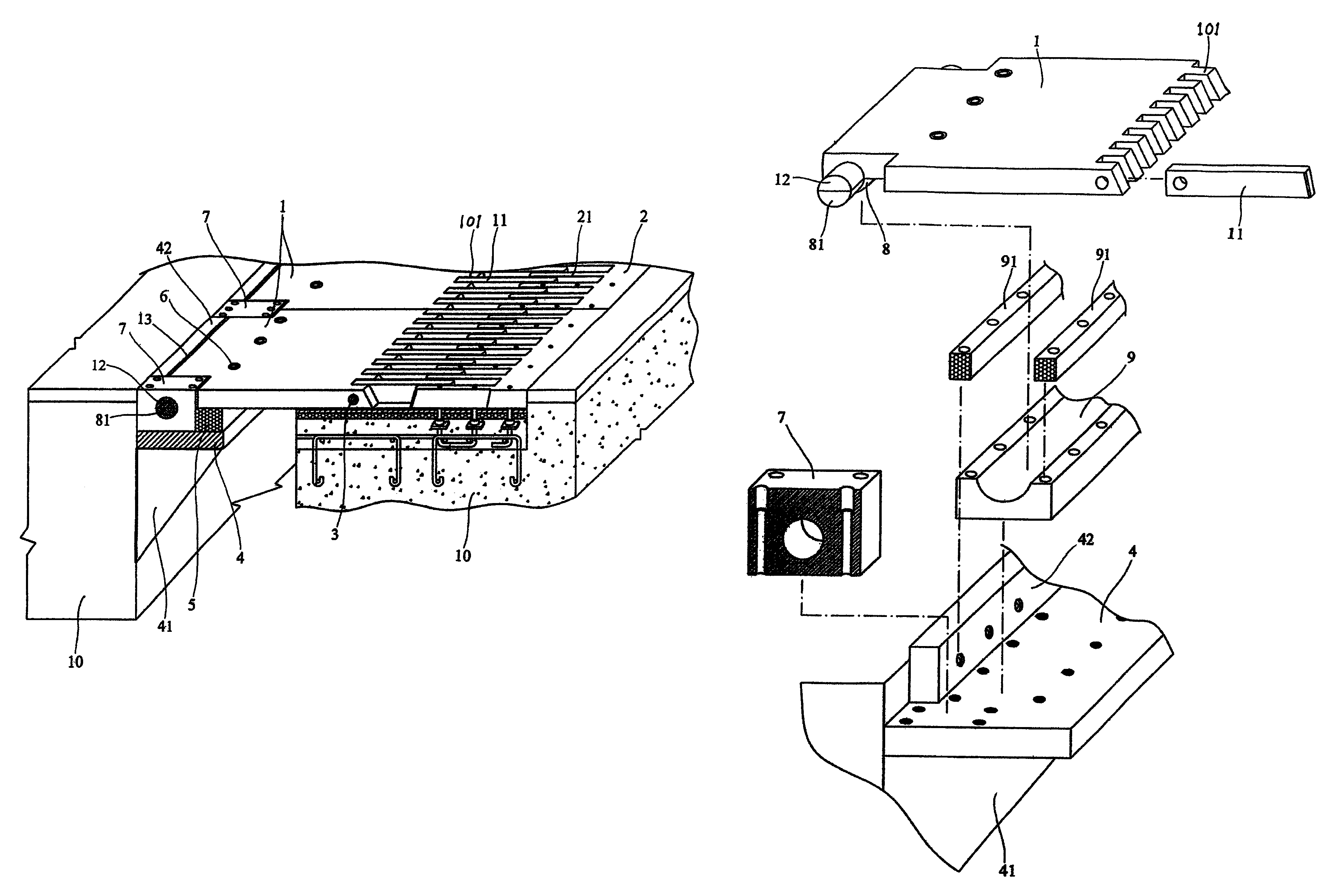
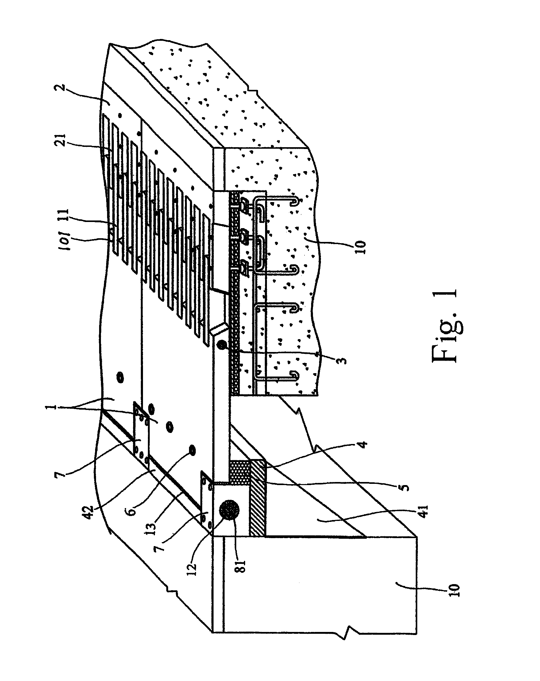
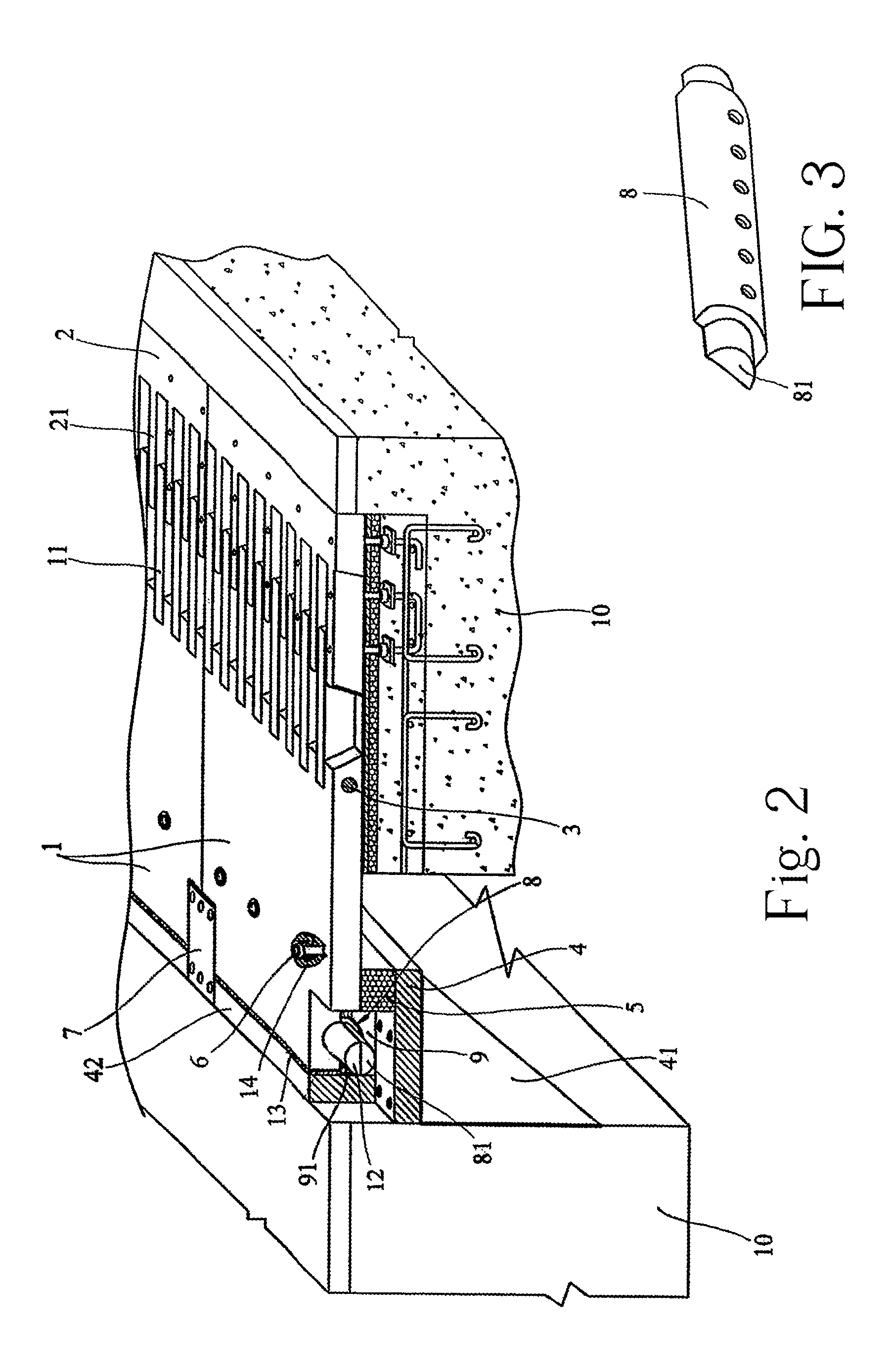
[0023]To enable a further understanding of the innovative and technological content of the invention herein, refer to the detailed description of the invention and the accompanying drawings below:

[0024]FIGS. 1˜4 shows the first embodiment of the present invention applied to steel girder. In this embodiment, the large resisting distortion comb-type bridge expansion joint comprises a fixed comb plate 2 and a movable comb plate 1 which are respectively disposed on the girders 10 located at the two sides of the bridge expansion joint. Every comb tooth 11 is pivoted by a shaft within the root teeth 101 on the first end of the movable comb plate 1, and the comb teeth 11 interdigitate with the comb teeth 21 of the fixed comb plate 2.

[0025]Matching the second end of the movable comb plate 1, a bracket which has a L-shaped section joints with the girder 10 by welding its stand side on the sidewall of the girder 10, and a triangle strengthening plate 41 is welded additionally between the brac...


PUM


Abstract

A large resisting distortion combo-type bridge expansion device, comprises fixed comb plate 2 and moveable comb plate 1 which are respectively disposed on the girder 10 where at the two sides of the bridge expansion device, the moveable comb plate 1 has comb teeth 11 interdigitate with the comb teeth 21 of the fixed comb plate, the moved comb plate 1 has a rotating shaft 8 at the bottom of its second end, and the two ends of the rotating shaft 8 pivot in the shaft seat 7 which is directly or indirectly fixed on the girders 10. In the present invention the second end of the moveable comb plate is rotatable, by which the moved comb plate will rotate round the girders when the girders have deflection distortion and the ends of the girders are raising or sinking. Therefore, the moved comb plate can keep flat to avoid damage of the expansion device, and to ensure that the vehicle can pass safely and smoothly.

Description

FIELD OF THE INVENTION[0001]The present invention relates to bridge expansion joints, in particular, to a large resisting distortion comb-type bridge expansion joint whose expansion amount can reach above 300 mm.DESCRIPTION OF THE PRIOR ART[0002]Among recent bridge expansion joints, a relatively good technique is the comb-type expansion joint, which comprises a fixed comb plate and a movable comb plate cooperating each other, and it is especially applied in the large bridge expansion joint whose expansion amount is more than 160 mm. For example, the Chinese patent No. ZL02264872.0 titled “Assemble Type Comb-type Bridge Expansion joint” invented by Bin Xu disclosed that the bridge expanding movement is provided by the movable comb plate, no lengthways transition space is existed between the fixed comb plate and the movable comb plate, and the joint connects the bridge surface and road surface as a whole, thereby, the ability of resisting vibration is very good, the vehicle can drive ...

Claims


Application Information

Patent Timeline
Patent Type & Authority Patents(United States)
IPC IPC(8): E01D19/06
CPCE01D19/06
Inventor XU, BIN
Owner XU BIN
Why Eureka
Try Eureka