Flow distributor apparatus for controlling spread width of a straw spreader

a distributor apparatus and spreader technology, applied in agriculture tools and machines, roads, constructions, etc., can solve the problems of uneven field warming and thawing, increased rodent and insect habitat, uneven distribution of crop residue, etc., and achieve better and more even distribution of crop residue.

Active Publication Date: 2008-06-24
BLUE LEAF I P INC
View PDF31 Cites 32 Cited by
  • Summary
  • Abstract
  • Description
  • Claims
  • Application Information

AI Technical Summary

Benefits of technology

[0009]There is thus disclosed herein a flow distributor apparatus for an agricultural combine which is operable for discharging a flow of straw or other crop residue in a sideward direction for deposit on and over a field, and, more particularly, a flow distributor apparatus that includes a flow guide or distributor element that is adjustably repositionable adjacent to counter-rotating spreader paddles to receive and direct the flow of crop residue therefrom. The flow distributor apparatus includes an adjusting mechanism which is operable to adjustably reposition the flow guide element relative to the spreader paddles to controllably adjust the clearance between the outer swept diameter of the spreader paddles and the crop residue flow surfaces of the flow guide element. Such changes in clearance alter and redirect the flow of crop residue so as to effect a desired pattern of crop residue flow from the spreader, such as to compensate for changing geographical and environmental conditions, in order that, under such conditions, a better and more even distribution of the crop residue may be realized over the entire width of the cut.
[0013]In accordance with one preferred embodiment of the invention, which is designed to address vertical movement of the flow guide element relative to the spreader paddles, the adjusting mechanism includes a cart or carriage assembly coupled to the flow guide element through the coupling connector for maintaining the flow guide element generally adjacent to the frontside of the back sheet or back plate of the spreader and for effecting generally vertical movement of the flow guide element relative to the spreader paddles. The cart or carriage assembly is generally vertically movable along the backside of the back plate of the spreader, such as under control of an electrically operable screw drive or linear actuator, and is preferably mounted at or beyond the back plate of the spreader. The coupling connector extends through an opening in the back plate of the spreader, which opening, for such embodiment, may be an elongated, generally vertical slot though which the coupling connector can extend and along which the coupling connector can be moved. Biasing elements, such as springs, may preferably be associated with the cart and utilized to provide a tension, applied through the coupling connector, to maintain the flow guide element in close association with or close proximity to the frontside of the back plate of the spreader, and an insert having a low coefficient of friction may be employed to minimize the effect of frictional forces between the aft end of the flow guide element and the back sheet or back plate of the spreader as the flow guide element is being repositioned or adjusted.

Problems solved by technology

With earlier spreaders, however, in many instances, uneven distribution of the crop residue occurred, with a greater or heavier concentration often being distributed nearer the center of the swath and a lesser or lighter concentration being distributed father sidewardly.
Such uneven distribution resulted in various problems such as, but not limited to, subsequent difficulty in passing fall tillage tools through residue clumps or thick areas, uneven insulation of the field, resulting in uneven field warming and thawing and subsequent uneven crop emergence during the following planting season, and other problems resulting from increased rodent and insect habitat.
However, such spreaders have continued to suffer from various shortcomings.
Many of such spreaders have exhibited a tendency to provide uneven crop residue distribution or coverage in the side to side direction over the swath, especially on uneven and varying terrain and in varying wind conditions.

Method used


Image

  • Flow distributor apparatus for controlling spread width of a straw spreader
  • Flow distributor apparatus for controlling spread width of a straw spreader
  • Flow distributor apparatus for controlling spread width of a straw spreader

Examples


Embodiment Construction

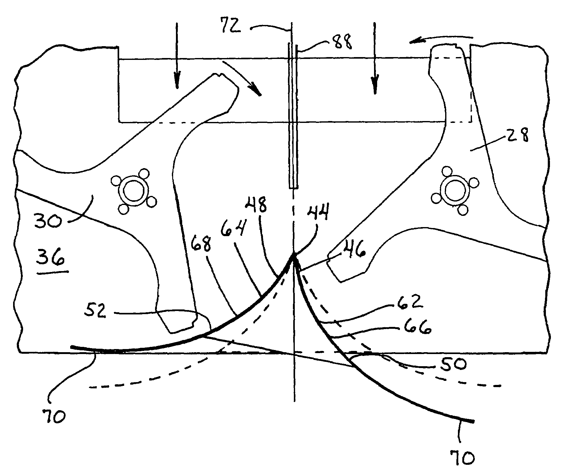
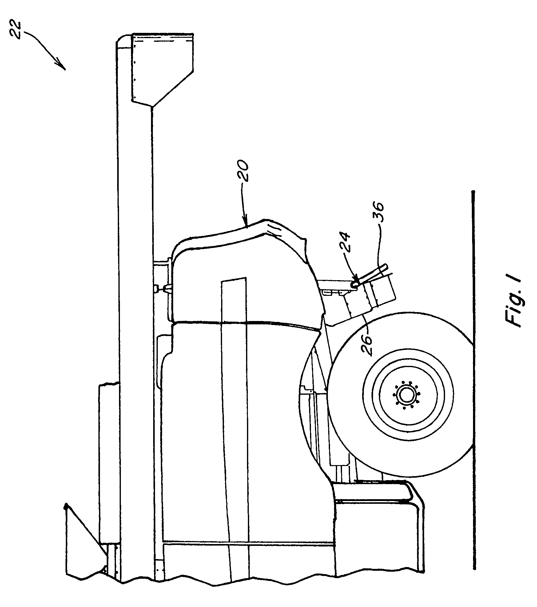
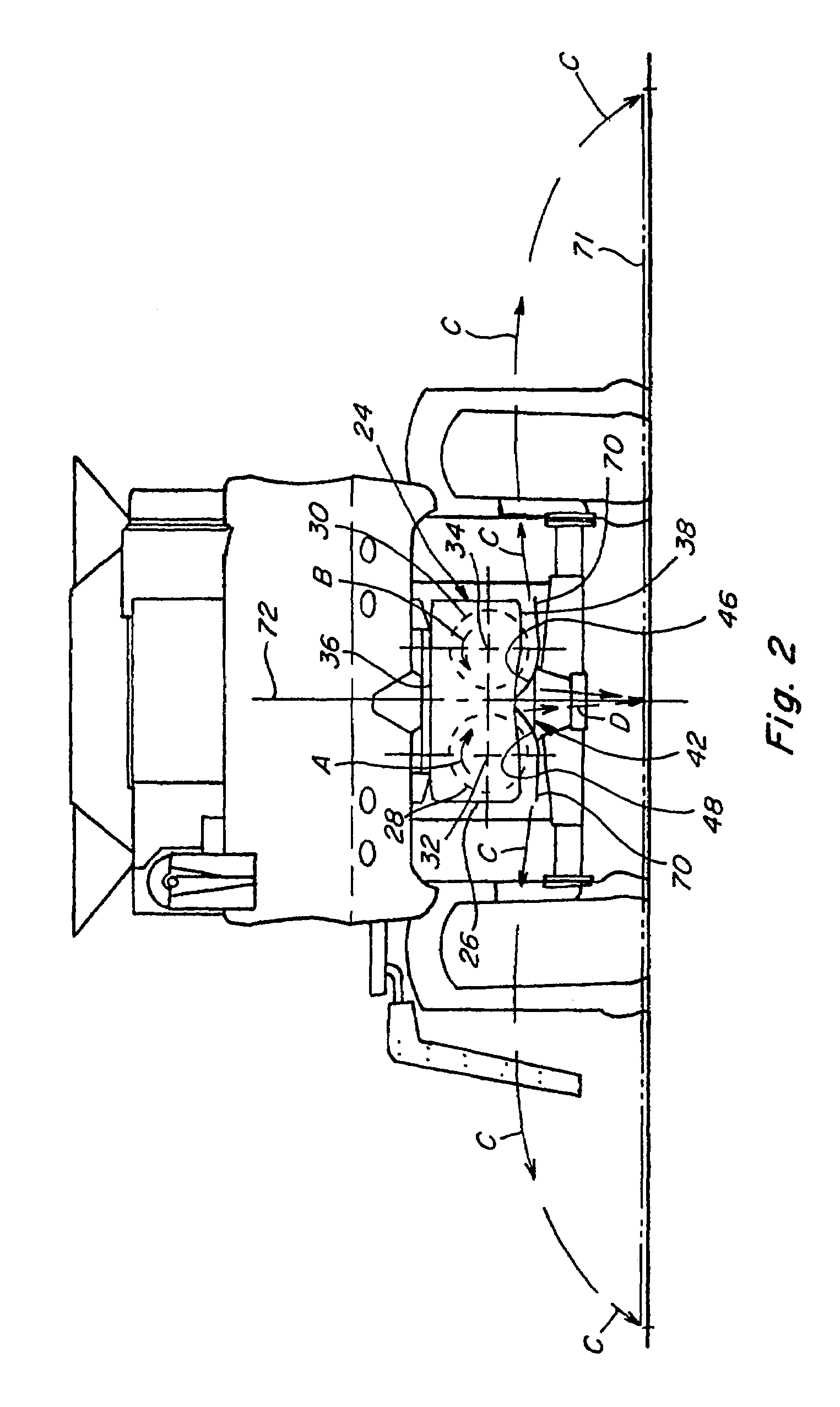
[0039]Referring now to the drawings, wherein preferred embodiments of the present invention are shown, wherein like numerals refer to like items, and wherein prime designators in conjunction with a numeral, e.g., 42′ and 42″, identify variations of the element designated by that numeral, FIG. 1 depicts a rear end 20 of a self-propelled agricultural combine 22, including a vertical crop residue spreader 24 operable for spreading straw, stalks, or other crop residue and trash that has been separated from the grain of the crops by a threshing mechanism (not shown) of combine 22 located forwardly of rear end 20. The straw, stalks and the like are propelled rearwardly by rotating beaters or the like (also not shown) from the threshing mechanism and downwardly through a rear cavity of combine 22 to vertical spreader 24, which includes within a housing 26 of sheet metal or other construction, components for effecting the spread and optional chopping of crop residue thereby, all in the well...


PUM


Abstract

A flow distributor apparatus for a vertical spreader operable for discharging a flow of straw or other crop residue in a sideward direction over a field, the flow distributor apparatus including a flow guide element, an adjusting mechanism, and a coupling connector connecting the flow guide element to the adjusting mechanism for controllable repositioning of the flow guide element relative to the spreader paddles. The flow guide element is disposed generally adjacent to the back plate of the spreader and intermediate the spreader paddles with an apex portion, laterally extending arm portions, and longitudinally extending crop residue flow surfaces, at least portions of which crop residue flow surfaces extend beneath the spreader paddles. The adjusting mechanism is operable to effect at least either vertical, horizontal, or rotational movement of the flow guide element relative to the spreader paddles to adjustably vary the clearances between the outer swept diameters of the spreader paddles and the crop residue flow surfaces to control the sidewardly outwardly discharge of crop residue from the spreader.

Description

[0001]This application claims the benefit of U.S. Provisional Application No. 60 / 808,369, filed May 25, 2006.TECHNICAL FIELD[0002]This invention relates generally to an agricultural combine and a flow distributor apparatus therefore which is operable for controlling the spread width discharge of a flow of straw or other crop residue in a sideward direction for deposit on and over a field, and the method of use thereof, and, more particularly, to an adjustably positionable flow guide element for a vertical spreader, which flow guide element is located generally intermediately adjacent to counter-rotating spreader paddles of the vertical spreader to receive and direct the flow of crop residue therefrom and is adjustably repositionable relative to the spreader paddles to controllably adjust the flow of crop residue to effect a desired pattern of crop residue flow therefrom, for instance, so as to better and more evenly distribute the flow side to side over a swath of an agricultural fi...

Claims


Application Information

Patent Timeline
Patent Type & Authority Patents(United States)
IPC IPC(8): A01F12/30
CPCA01D41/1243
Inventor FARLEY, HERBERT M.ISAAC, NATHAN E.LAUWERS, ANDREW V.BENES, JASON M.
Owner BLUE LEAF I P INC
Why Eureka
Try Eureka