Torque-coupling device for front-wheel-drive transaxle unit

a transaxle unit and torque coupling technology, which is applied in mechanical equipment, transportation and packaging, and open differentials known in the art, can solve the problems of unsuitable differentials, i.e. differentials without clutches or springs, and the limited-slip differential in the fwd transaxle unit is extremely difficult to package, so as to enhance the mobility of fwd vehicles, maintain fuel economy of two-wheel drive motor vehicles, and minimize wheelspin

Active Publication Date: 2008-06-24
DANA AUTOMOTIVE SYST GRP LLC
View PDF24 Cites 14 Cited by
  • Summary
  • Abstract
  • Description
  • Claims
  • Application Information

AI Technical Summary

Benefits of technology

[0010]Therefore, the front-wheel-drive transaxle unit in accordance with the present invention includes the torque-coupling device providing the differential assembly with the limited-slip function only when required, and performs as an open differential when sufficient torque is developed, thus enhancing FWD vehicle mobility, minimizing wheelspin, and providing the FWD vehicle with the mobility performance approaching that of an all-wheel-drive system at a fraction of the cost, while maintaining fuel economy of a two-wheel-drive motor vehicle. The present invention provides the FWD transaxle unit with the torque-coupling device in a compact packaging while avoiding major transaxle redesign.

Problems solved by technology

However, these types of differentials known in the art as an open differentials, i.e. a differential without clutches or springs, are unsuitable in slippery conditions where one wheel experiences a much lower coefficient of friction than the other wheel; for instance, when one wheel of a vehicle is located on a patch of ice or mud and the other wheel is on dry pavement.
In such a condition, the wheel experiencing the lower coefficient of friction loses traction and a small amount of torque to that wheel will cause a “spin out” of that wheel.
Packaging the limited-slip differential in the FWD transaxle unit is extremely difficult due to space limitations, and the FWD transaxle housings cannot be economically redesigned to allow for more space.

Method used


Image

  • Torque-coupling device for front-wheel-drive transaxle unit
  • Torque-coupling device for front-wheel-drive transaxle unit
  • Torque-coupling device for front-wheel-drive transaxle unit

Examples


Embodiment Construction

[0016]The preferred embodiment of the present invention will now be described with the reference to accompanying drawings.

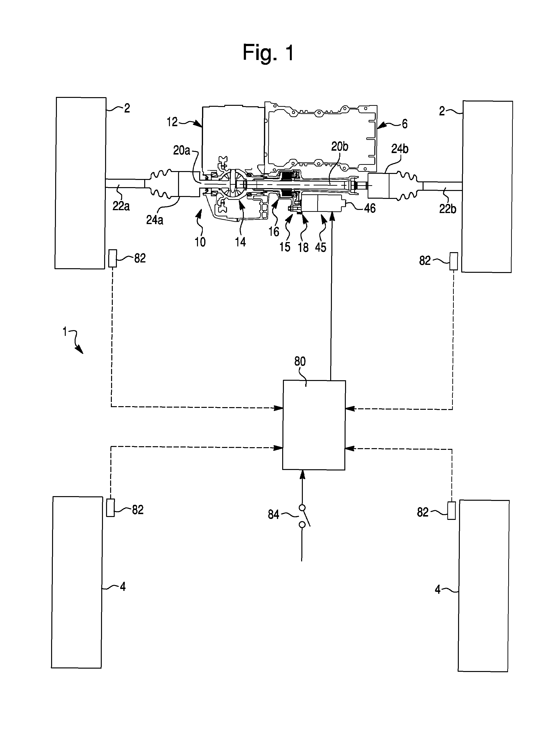
[0017]FIG. 1 of the drawings schematically illustrates a layout of a motor vehicle drivetrain of a front-wheel-drive (FWD) motor vehicle 1 with a transversely mounted front engine suited for use with the present invention. The motor vehicle 1 has a pair of the front drive wheels 2, a pair of rear drive wheels 4 and a front-wheel-drive (FWD) transaxle unit 10 positioned between the two front wheels 2. The FWD transaxle unit 10 is operatively connected to a prime mover 6, such as an internal combustion engine, electric motor, etc. More specifically, the engine 6 has a transversely extending crankshaft 8 with its left-hand end splined to the FWD transaxle unit 10.

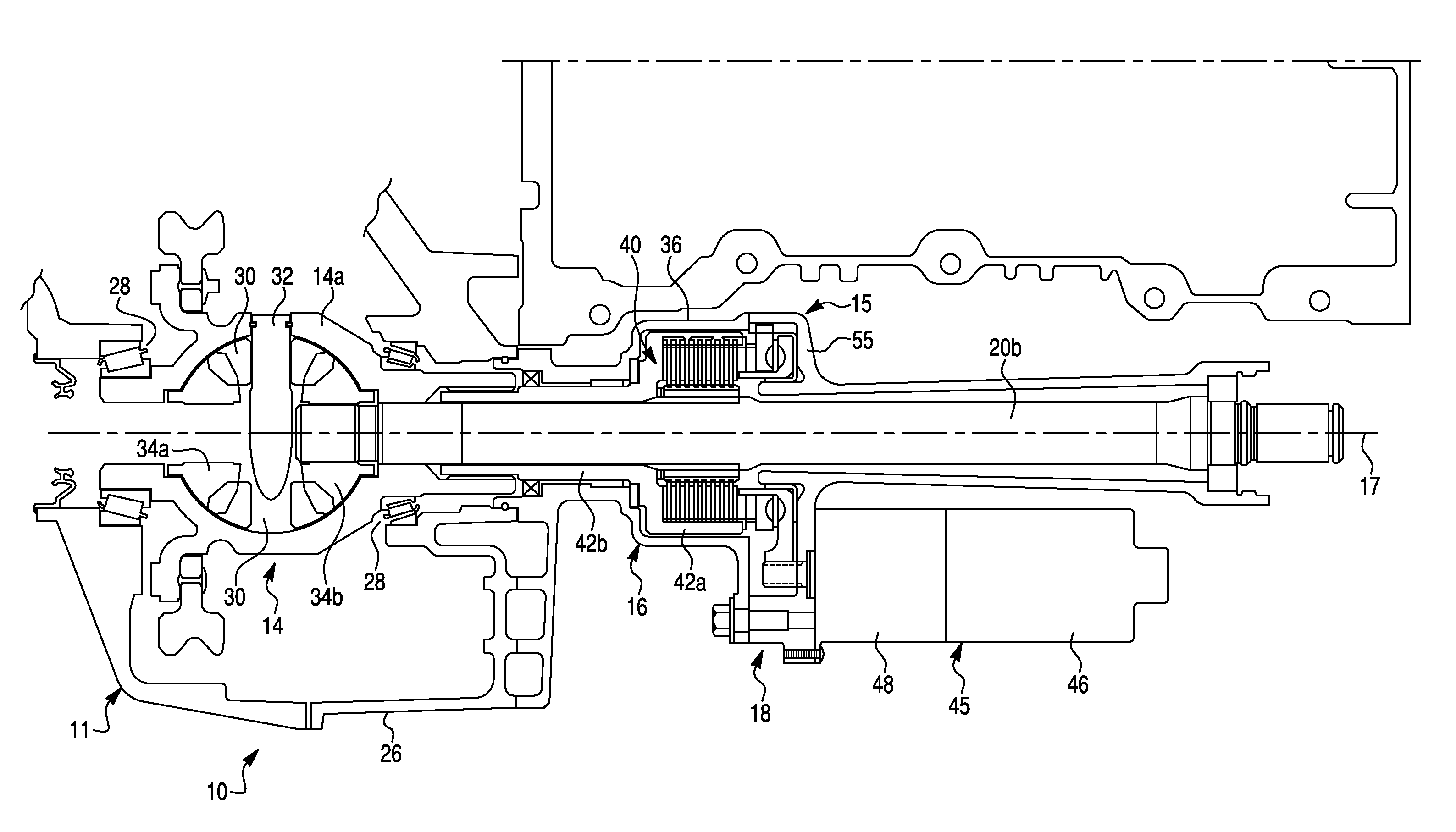
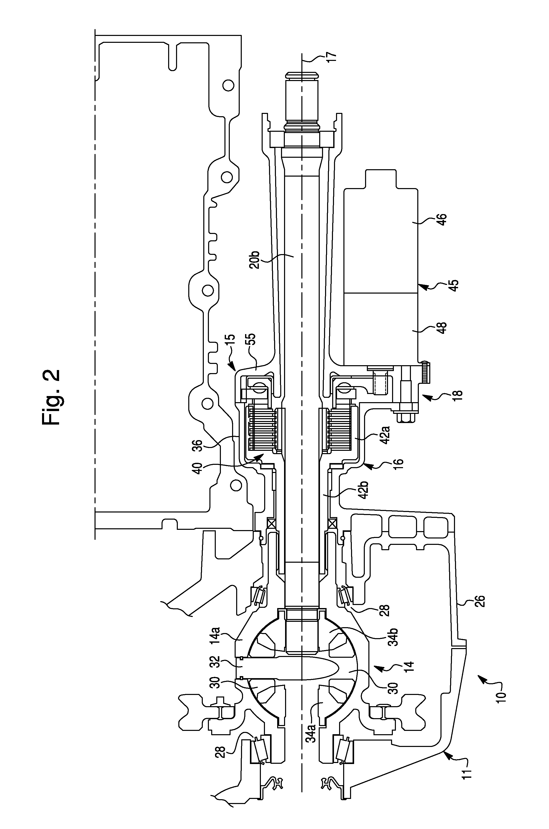
[0018]The FWD transaxle unit 10 is a drive setup in which a power transmission 12, a final drive, and a differential assembly 14 are combined into a single unit connected directly to the engine 6. The FWD t...


PUM


Abstract

A front-wheel-drive transaxle unit for a motor vehicle comprises a differential assembly having a differential mechanism disposed in a differential case and two opposite output shafts outwardly extending from the differential case and a torque-coupling device for selectively restricting differential rotation of the differential mechanism. The torque-coupling device includes a friction clutch assembly for selectively frictionally engaging and disengaging the differential case and one of the output shafts, and a selectively controllable clutch actuator assembly for selectively frictionally loading the friction clutch assembly. The clutch assembly includes at least one first member non-rotatably coupled to the differential case and at least one second member non-rotatably coupled to one of said output shafts. The torque-coupling device provides the differential assembly of the front-wheel-drive transaxle unit with both limited-slip and open differential capabilities.

Description

BACKGROUND OF THE INVENTION[0001]1. Field of the Invention[0002]The present invention relates to front wheel drive transaxle units for a motor vehicle, and more particularly to a front wheel drive transaxle unit having a differential assembly and a torque-coupling device providing the differential assembly with a limited slip capability.[0003]2. Description of the Prior Art[0004]Conventionally, differentials well known in the prior art, are arranged in a power transmission system of a motor vehicle to allow a pair of output axle shafts operatively coupled to an input shaft to rotate at differential speeds, thereby allowing the wheel associated with each output shaft to maintain traction with the road while the vehicle is turning. Such a device essentially distributes the torque provided by the input shaft between the output shafts. However, these types of differentials known in the art as an open differentials, i.e. a differential without clutches or springs, are unsuitable in slipp...

Claims


Application Information

Patent Timeline
Patent Type & Authority Patents(United States)
IPC IPC(8): F16H48/30F16H48/06F16H48/20
CPCF16H48/08F16H48/22F16H48/295F16H48/30F16H48/34B60K17/20F16H2048/204F16H2048/343B60K17/105
Inventor KRISHER, JAMES A.
Owner DANA AUTOMOTIVE SYST GRP LLC
Why Eureka
Try Eureka