System and methods for reducing particulate matter emissions

a technology of particulate matter and system, applied in the direction of machines/engines, output power, electric control, etc., can solve the problems of increasing the cost of the drivetrain, and unnecessarily reducing the fuel economy of the engine operating, so as to reduce the emission of soot and other particulate matter (pm), increasing the complexity of the drivetrain, and reducing the engine performance and fuel economy

Active Publication Date: 2019-11-26
FORD GLOBAL TECH LLC
View PDF26 Cites 0 Cited by
  • Summary
  • Abstract
  • Description
  • Claims
  • Application Information

AI Technical Summary

Benefits of technology

[0014]In this way, the fuel oxygen content may be more rapidly adjusted to achieve the technical result of maintaining a PM at or below a target level without a DPF over a broad range of engine designs and operating conditions, while maintaining fuel economy. Furthermore, by adjusting an opening of one or more of the VCV and the PCV, adjustments to fuel oxygen content can be more responsive, further reducing PM emissions and increasing fuel economy. Further still, CO2 emissions may be reduced due to reduced exhaust system back pressure from the elimination of the DPF, which in turn can increase engine power and torque, and may enable significant engine downsizing. Further still, the technical result of eliminating the DPF from the exhaust system lowers manufacturing costs and may enable further cost reductions for other related engine components such as the NOx aftertreatment or the EGR system. Eliminating the DPF from the exhaust system also eliminates the need for DPF regeneration which further reduces PM and CO2 emissions and increases fuel economy. Further still, in a vehicle system engine comprising a DPF, the methods and systems described herein may be utilized to reduce frequency of DPF regeneration, thereby reducing both fuel consumption and PM emissions, and prolonging a life of the DPF.

Problems solved by technology

However, DPFs increase drivetrain cost, complexity, and weight, and can reduce engine performance and fuel economy.
However, the inventors herein have recognized various issues with the above approach.
Accordingly, combustion of a fuel having a higher fuel oxygen content may overly penalize or may unnecessarily reduce the fuel economy of an engine operating under conditions where PM emissions are inherently lower.

Method used


Image

  • System and methods for reducing particulate matter emissions
  • System and methods for reducing particulate matter emissions
  • System and methods for reducing particulate matter emissions

Examples


Embodiment Construction

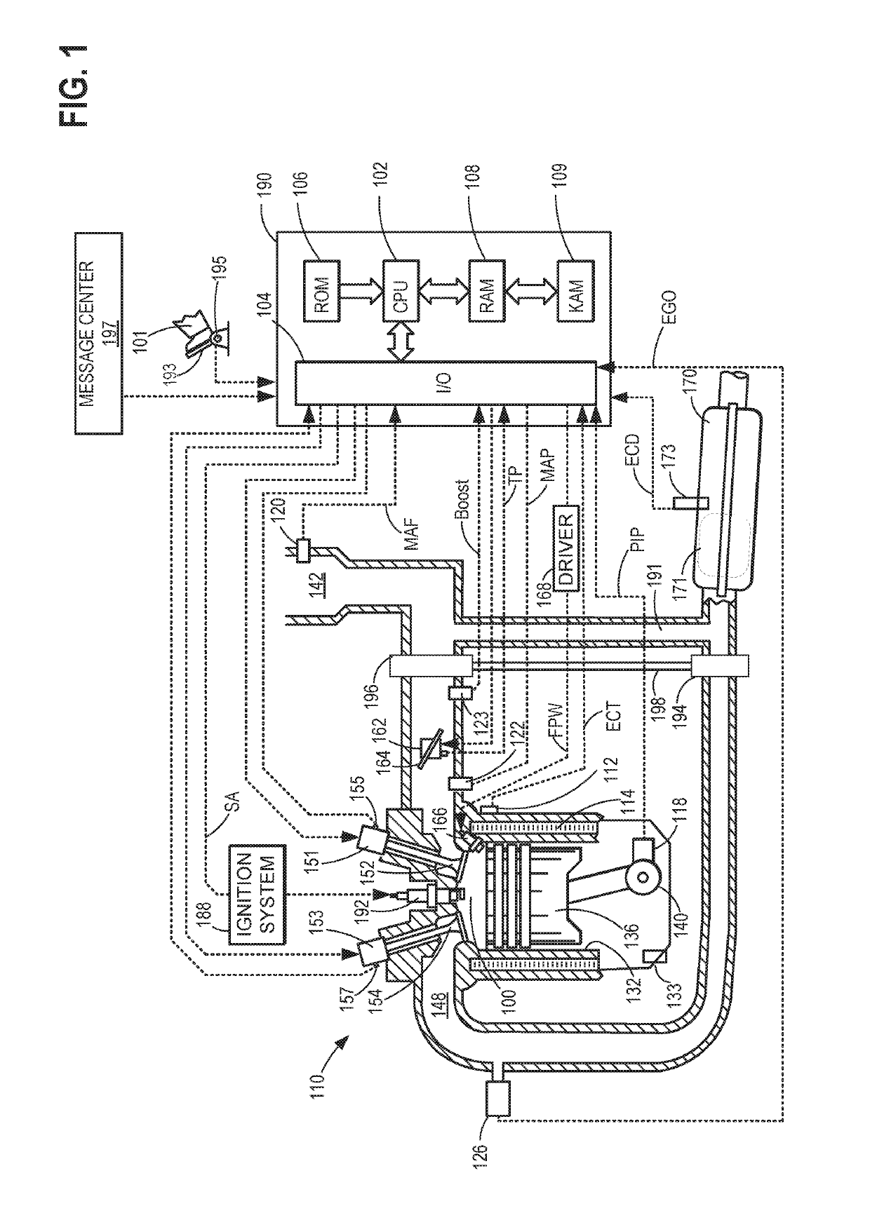
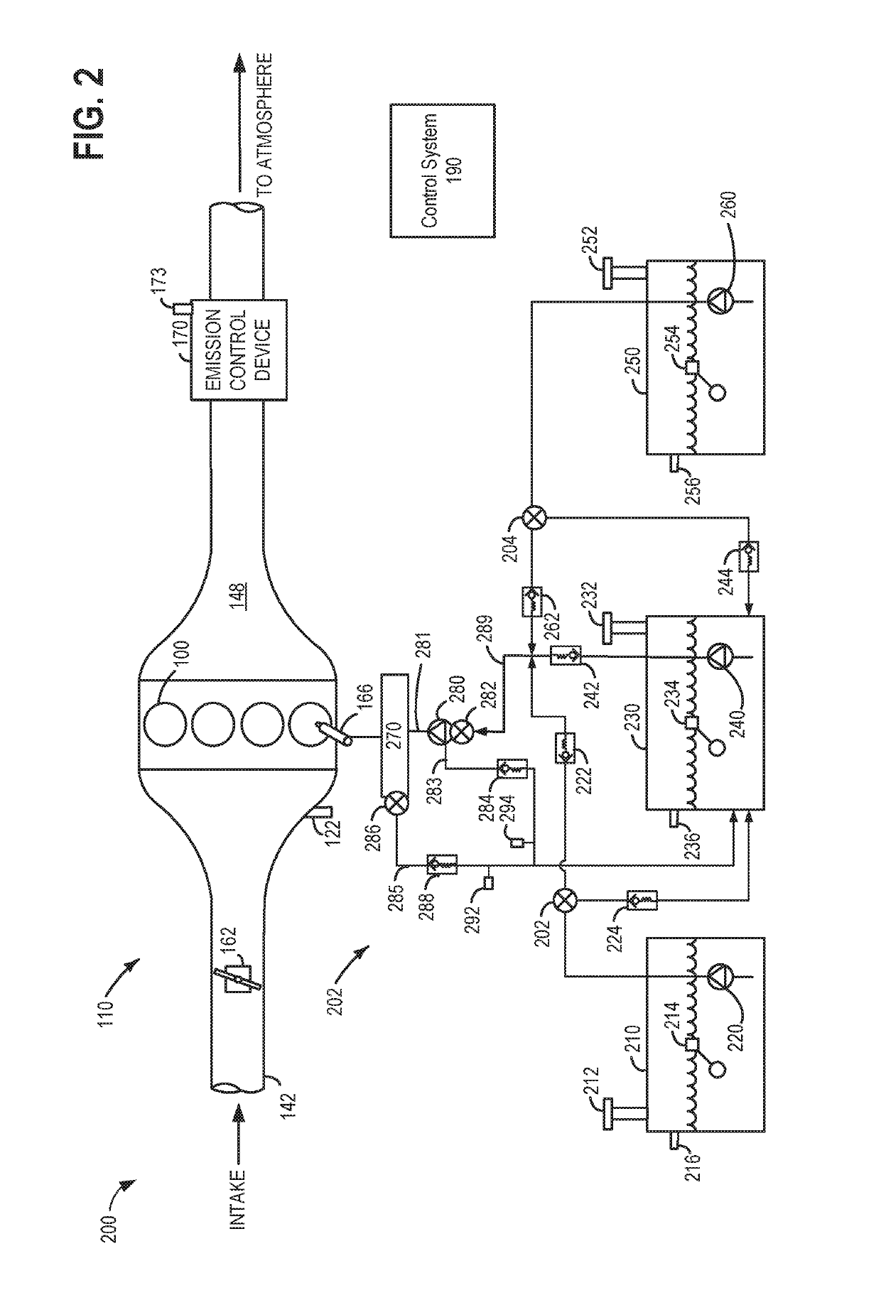
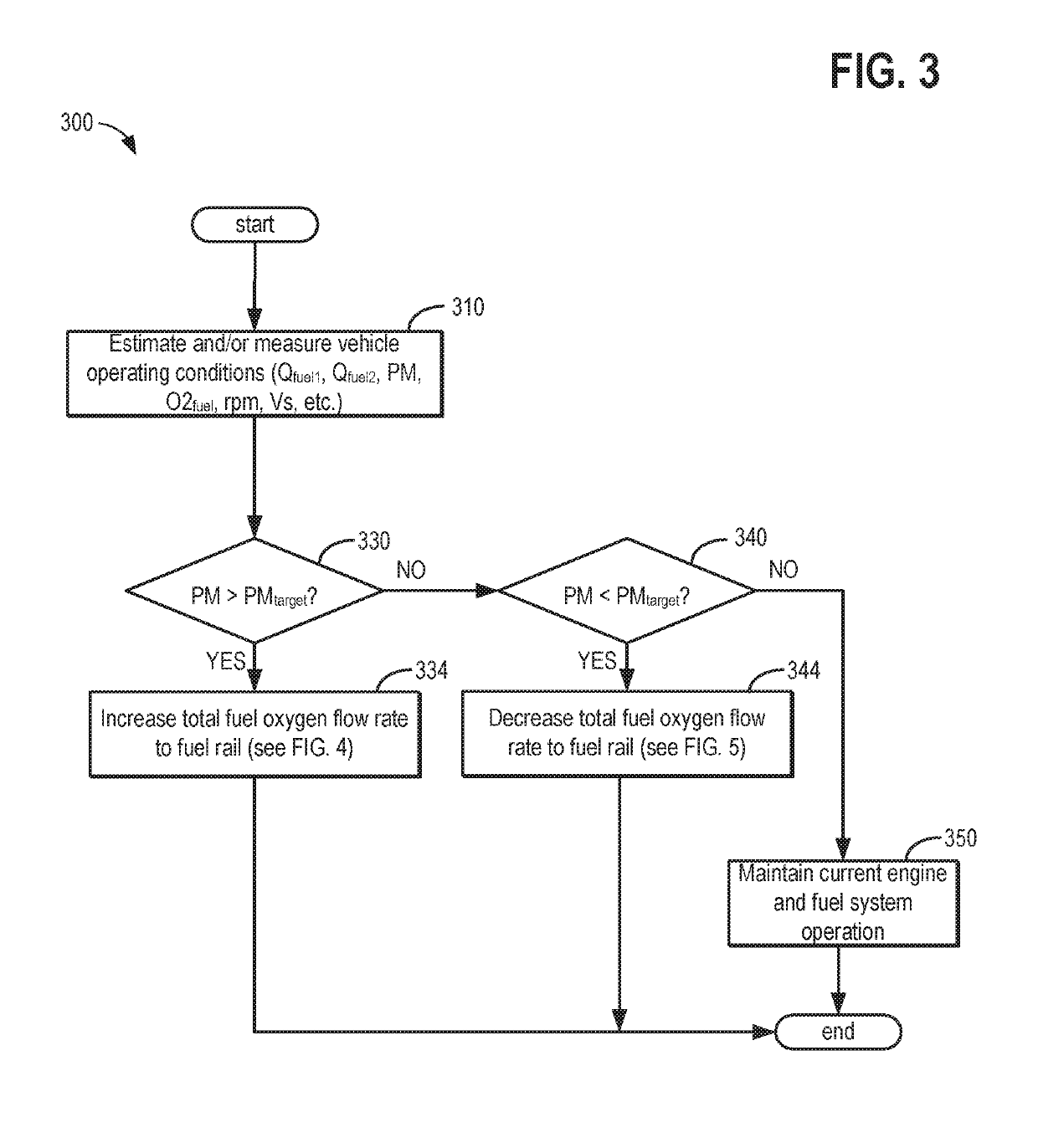
[0013]This detailed description relates to systems and methods for reducing particulate matter (PM) emissions from a vehicle combustion engine, such as the engine of FIG. 1. In response to a PM level deviating from a target PM level in the engine, fuel oxygen content delivered to the engine from the fuel system shown in FIG. 2 may be adjusted. In particular, a controller may perform executable instructions, as shown in the flow charts of FIGS. 3-6, to adjust the fuel oxygen content delivered to the engine responsive to a PM level deviating from the target PM level. Furthermore, the controller may perform executable instructions, as shown in the flow chart of FIGS. 3-6, to open of one or more of a volume control valve (VCV) and a pressure control valve (PCV) responsive to the exhaust PM deviating from the target PM, and responsive to the fuel oxygen content deviating from a target fuel oxygen content. As shown in the fuel system of the engine in FIG. 2, the VCV may be positioned at a...


PUM


Abstract

A method may comprise: positioning a pressure control valve (PCV) at an outlet of a fuel rail; positioning a volume control valve (VCV) at an inlet of a high pressure pump; and in response to an exhaust particulate matter (PM) level deviating from a target PM level, adjusting a fuel ratio of a first fuel and a second fuel delivered to an engine, and opening one of the PCV and the VCV. In this way, the fuel oxygen content may be adjusted to maintain a PM at or below a target level without a DPF over a broad range of engine designs and operating conditions, while maintaining fuel economy.

Description

BACKGROUND AND SUMMARY[0001]Diesel engines commonly include diesel particulate filters (DPFs) to reduce emission of soot and other particulate matter (PM) from diesel fuel combustion. However, DPFs increase drivetrain cost, complexity, and weight, and can reduce engine performance and fuel economy. Increasing the fuel oxygen content is one method that may reduce the PM emission levels such that a DPF may be foregone. Introduction of a higher oxygen-containing fuel into the engine combustion chambers may promote more uniform combustion and reduce fuel-rich regions within the combustion chambers, where soot and PM tend to form.[0002]However, the inventors herein have recognized various issues with the above approach. Namely, a fuel oxygen content corresponding to a large enough reduction in PM to meet engine emissions standards (without a DPF) depends on many factors, including the design of the engine and combustion system. Accordingly, combustion of a fuel having a higher fuel oxyge...

Claims


Application Information

Patent Timeline
Patent Type & Authority Patents(United States)
IPC IPC(8): F02D41/02F02D19/08F02D41/00F02D19/06F02D41/38F02D13/02F01N11/00F02D41/14
CPCF02D41/3863F02D19/0678F02D41/3845F02D19/0628F02D19/084F02D41/0025F02D19/0694F02D41/1466F02D19/0607F02D19/0665F02D19/081F01N11/007F02D41/029F01N2900/1402Y02T10/36F02D13/0215F01N2560/05F02D19/0684Y02T10/30
Inventor KURTZ, ERIC MATTHEWPOLONOWSKI, CHRISTOPHERANDERSON, JAMES ERICWILLEMS, WERNERROBARGE, NAN
Owner FORD GLOBAL TECH LLC
Why Eureka
Try Eureka