
Control device and control method for an internal combustion engine

a control device and control method technology, applied in the direction of electric control, combustion engines, machines/engines, etc., can solve the problems of increased supercharging pressure, increased exhaust loss, engine breakage, etc., to maintain fuel economy and improve acceleration performance.

Active Publication Date: 2015-06-16
MITSUBISHI ELECTRIC CORP
View PDF3 Cites 0 Cited by
  • Summary
  • Abstract
  • Description
  • Claims
  • Application Information

AI Technical Summary

Benefits of technology

[0013]The present invention has been made to solve the problems described above, and it is an object of the present invention to provide a control device and a control method for an internal combustion engine, capable of improving acceleration performance while maintaining fuel performance.
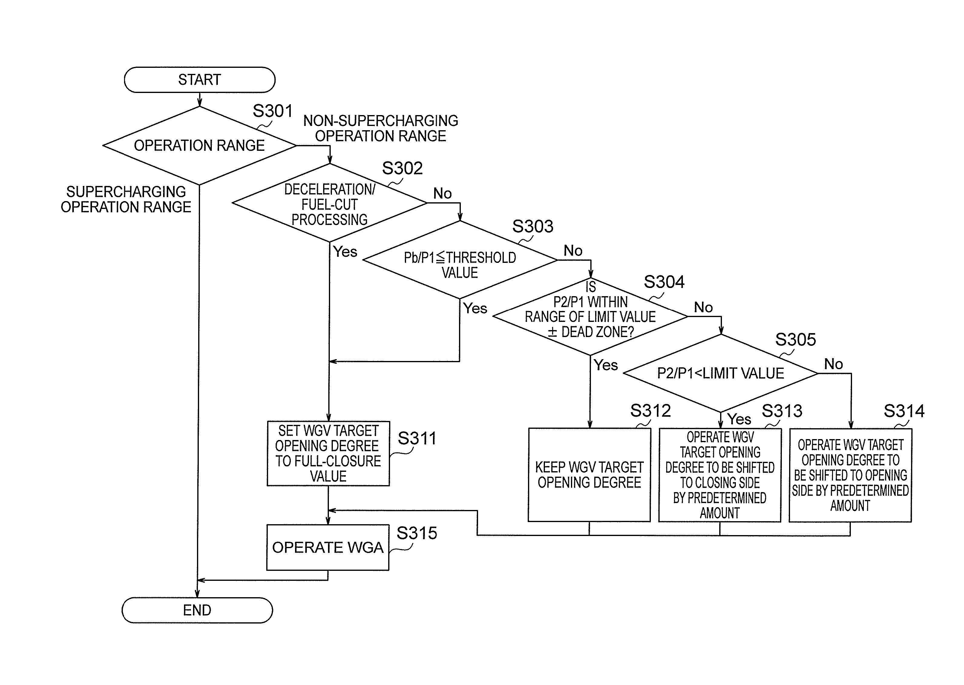
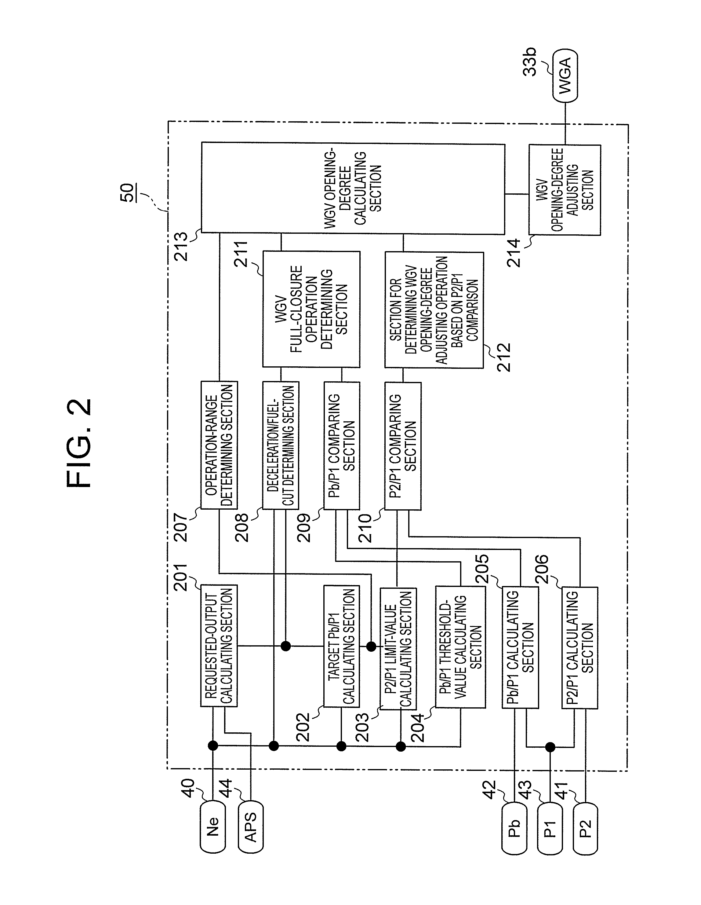
[0015]The control device for an internal combustion engine according to the exemplary embodiment of the present invention, the internal combustion engine including: the throttle valve provided in the intake passage of the internal combustion engine; the supercharger including the turbine provided in the exhaust passage of the internal combustion engine and the compressor provided upstream of the throttle valve in the intake passage, the compressor being configured to rotate integrally with the turbine; the wastegate valve provided in the bypass passage, the bypass passage being provided to the exhaust passage so as to bypass the turbine; the wastegate-valve driving section for changing the flow-path sectional area of the bypass passage by driving the wastegate valve; the intake-manifold pressure detecting section for detecting the pressure of the intake manifold (Pb) provided downstream of the throttle valve; the atmospheric-pressure detecting section for detecting the atmospheric pressure (P1) outside of the internal combustion engine; the accelerator operation-amount detecting section for detecting the operation amount of the accelerator by the driver; and the rpm sensor for detecting the rpm of the internal combustion engine, includes: the operation-range detecting section for determining, based on the operation amount of the accelerator and the rpm of the internal combustion engine, whether the operation range requested by the driver is the supercharging operation range or the non-supercharging operation range; a Pb / P1 comparing section for determining whether the ratio of the pressure of the intake manifold and the atmospheric pressure is smaller than the threshold value when the operation range is the non-supercharging operation range; the WGV opening-degree calculating section for calculating the target opening degree of the wastegate valve based on the ratio of the pressure of the intake manifold and the atmospheric pressure; and the WGV opening-degree adjusting section for adjusting the opening degree of the wastegate valve based on the target opening degree calculated by the WGV opening-degree calculating section, in which the WGV opening-degree calculating section calculates, as the full-closure value, the target opening degree of the wastegate valve when the ratio of the pressure of the intake manifold and the atmospheric pressure is smaller than the threshold value. Therefore, it is possible to improve the acceleration performance while maintaining the fuel economy.

Problems solved by technology

In a state in which the engine rotates at a high speed under a high load, The turbocharger has a fear in that a supercharging pressure is increased to become larger than needed with the result that the engine is broken.
As the exhaust pressure increases, an exhaust loss becomes larger to lower the efficiency of the engine.
As a result, there arises a problem in that acceleration performance of the engine is degraded.
However, the method described in Japanese Patent Application Laid-open No. 2006-274831 has the following problem.

Method used


Image

  • Control device and control method for an internal combustion engine
  • Control device and control method for an internal combustion engine
  • Control device and control method for an internal combustion engine

Examples


first embodiment

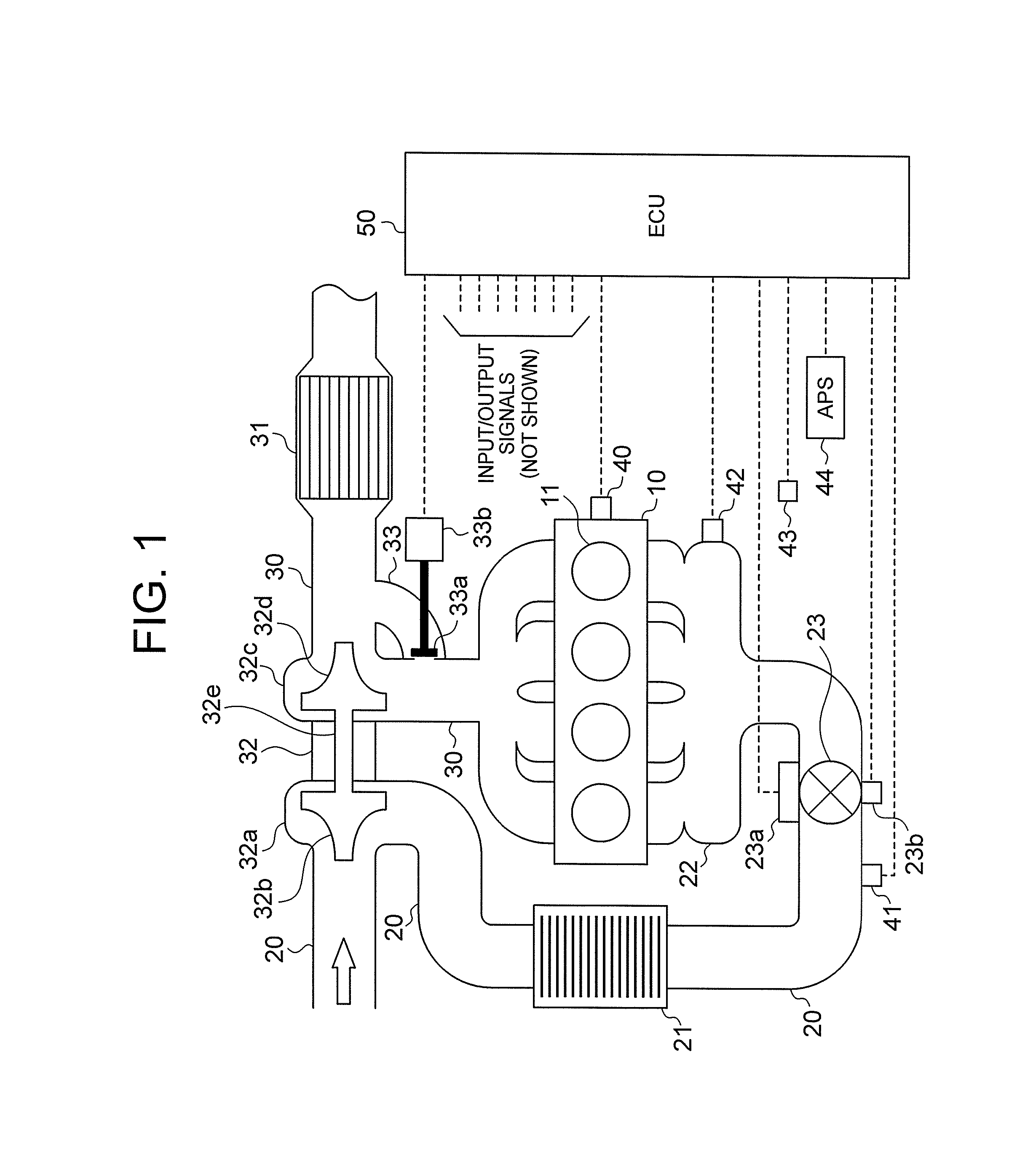
[0024]In the following, a control device for an internal combustion engine according to an embodiment of the present invention is described referring to the accompanying drawings. FIG. 1 is a diagram illustrating a schematic configuration of an internal combustion engine (hereinafter referred to simply as “engine”) and a control device therefor according to a first embodiment of the present invention.

[0025]An engine 10 includes a plurality of combustion chambers 11. An intake passage 20 and an exhaust passage 30 are connected to the engine 10 through an intake manifold 22. To the exhaust passage 30, a turbine housing 32c of a turbocharger 32 is provided. In a region of the exhaust passage 30, which is located upstream of the turbine housing 32c (hereinafter referred to simply as “upstream region”) is coupled to a region of the exhaust passage 30, which is located downstream of the turbine housing 32c (hereinafter referred to simply as “downstream region”) through a bypass passage 33...


PUM


Abstract

Provided is a control device for an internal combustion engine, which improves acceleration performance while maintaining fuel performance in a non-supercharging operation range. A bypass passage (33) which bypasses a turbine (32c, 32d) of a supercharger is provided. In the bypass passage (33), a wastegate valve (33a) for adjusting a flow-path area of the bypass passage (33) by a wastegate actuator (33b) is provided. For an operation in the non-supercharging operation range, an opening degree of the wastegate valve (33a) is set to fully close the wastegate valve (33a) when a ratio of a pressure (Pb) of an intake manifold (22) and an atmospheric pressure (P1) is smaller than a threshold value.

Description

BACKGROUND OF THE INVENTION[0001]1. Field of the Invention[0002]The present invention relates to a control device and a control method for an internal combustion engine, and more particularly, to a control device for an internal combustion engine in which a supercharger is mounted, for example.[0003]2. Description of the Related Art[0004]There has been known a turbocharger having a supercharger that operates by rotating a turbine by using an exhaust gas, which is mounted in an intake passage of an internal combustion engine (hereinafter referred to simply as “engine”) for the purpose of improvement of an output of the engine. In the following, an operation range in which supercharging is performed by the supercharger is referred to as a supercharging operation range, whereas an operation range in which the supercharging is not performed by the supercharger is referred to as a non-supercharging operation range.[0005]In a state in which the engine rotates at a high speed under a high ...

Claims


Application Information

Patent Timeline
Patent Type & Authority Patents(United States)
IPC IPC(8): F02D23/00F02D41/00F02B37/18F02B33/44F02D41/10
CPCF02B37/183F02B37/18F02D41/0007F02D41/10Y02T10/144F02D2200/0406F02D2200/101F02D2200/602F02D2200/703F02D2250/22Y02T10/12
Inventor YOKONO, MICHIHISAMAKINO, TOMOKAZUONO, TAKAHIKO
Owner MITSUBISHI ELECTRIC CORP
Learn More