Method and system for fuel system control

a fuel system and control method technology, applied in the field of fuel systems, can solve the problems of reducing the efficiency of jet pumps, and low fuel tank and jet pump fuel reservoir levels, so as to maintain the flow and performance of jet pumps, reduce the pressure drop of large di fuel rails, and preserve the efficiency of di pumps.

Active Publication Date: 2017-06-27
FORD GLOBAL TECH LLC
View PDF44 Cites 3 Cited by
  • Summary
  • Abstract
  • Description
  • Claims
  • Application Information

AI Technical Summary

Benefits of technology

[0003]However, the inventors herein have identified potential issues with such systems. The lift pump pressures applied to maintain DI pump efficiency may be low, especially during cold fuel conditions, thereby reducing performance of jet pumps inside the fuel tank, which can cause low fuel tank and jet pump fuel reservoir levels. Low fuel tank and low jet pump fuel reservoir levels can lead to low fuel line pressures, fuel vaporization within the fuel system, and a precipitous drop in DI fuel rail pressure, causing the engine to stall.
[0004]In one example, the above issues may be addressed by a method comprising: increasing a lift pump voltage to a high threshold voltage responsive to a DI pump volumetric efficiency being below a threshold volumetric efficiency, and increasing a lift pump voltage to a first threshold voltage less than the high threshold voltage responsive to a main jet pump fuel reservoir level being less than a first threshold reservoir level. In this way, the technical result of maintaining jet pump fuel flow and performance while preserving DI pump efficiency may be achieved. Accordingly, a risk of fuel vaporization within the liquid fuel delivery system and large DI fuel rail pressure drops can be reduced, and engine operation robustness may be increased while maintaining fuel economy.
[0005]In one example, if the DI pump volumetric efficiency decreases below a threshold volumetric efficiency, the lift pump voltage will be increased to a high threshold voltage in order to mitigate the DI pump volumetric efficiency drop and to restore the DI pump volumetric efficiency to the threshold volumetric efficiency. Furthermore, in response to a fuel reservoir fuel level decreasing below a first threshold reservoir fuel level, the lift pump voltage may be increased to a second threshold voltage less than the high threshold voltage. In this manner, both engine operation with low DI fuel pump efficiency, and fuel vaporization arising from low fuel reservoir levels and low jet pump flow can be mitigated while preserving fuel economy.

Problems solved by technology

However, the inventors herein have identified potential issues with such systems.
The lift pump pressures applied to maintain DI pump efficiency may be low, especially during cold fuel conditions, thereby reducing performance of jet pumps inside the fuel tank, which can cause low fuel tank and jet pump fuel reservoir levels.
Low fuel tank and low jet pump fuel reservoir levels can lead to low fuel line pressures, fuel vaporization within the fuel system, and a precipitous drop in DI fuel rail pressure, causing the engine to stall.

Method used


Image

  • Method and system for fuel system control
  • Method and system for fuel system control
  • Method and system for fuel system control

Examples


Embodiment Construction

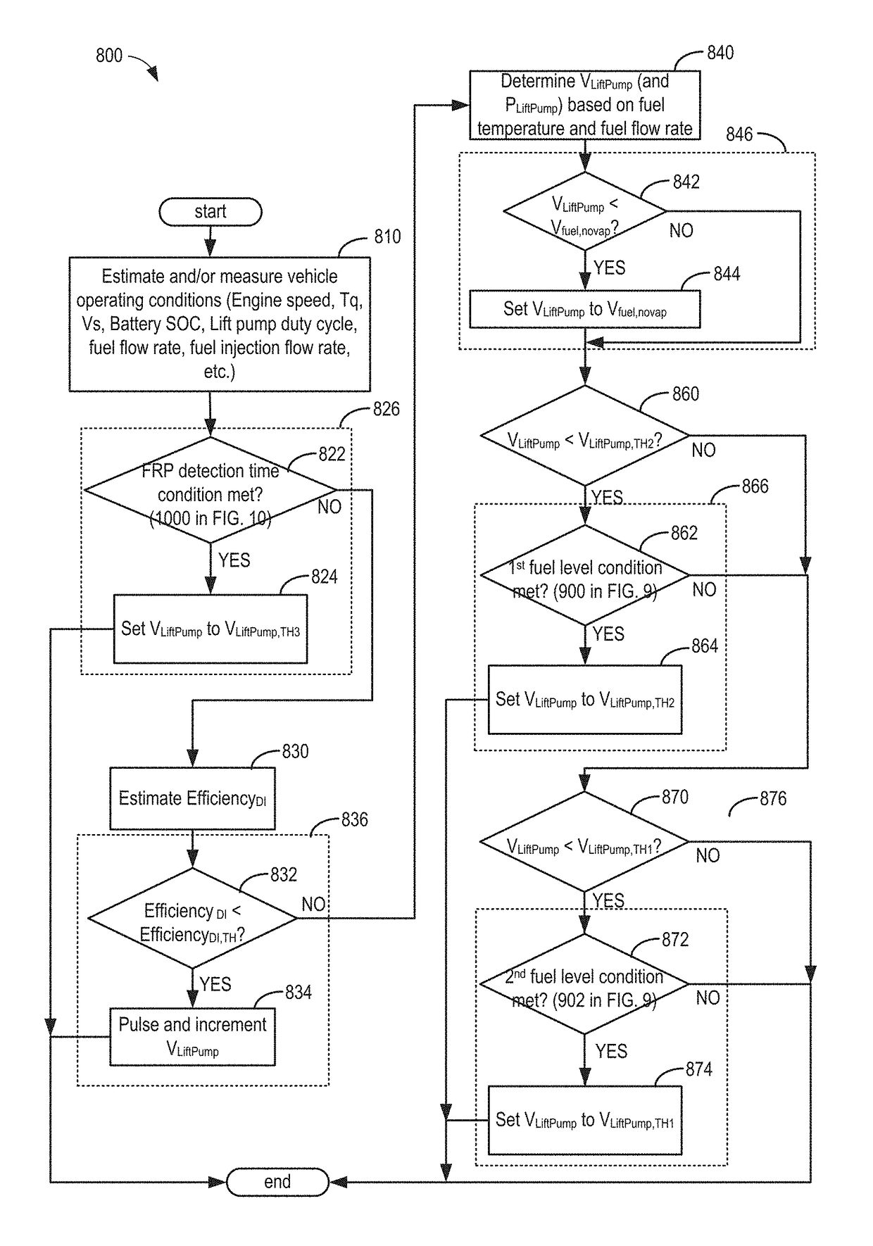
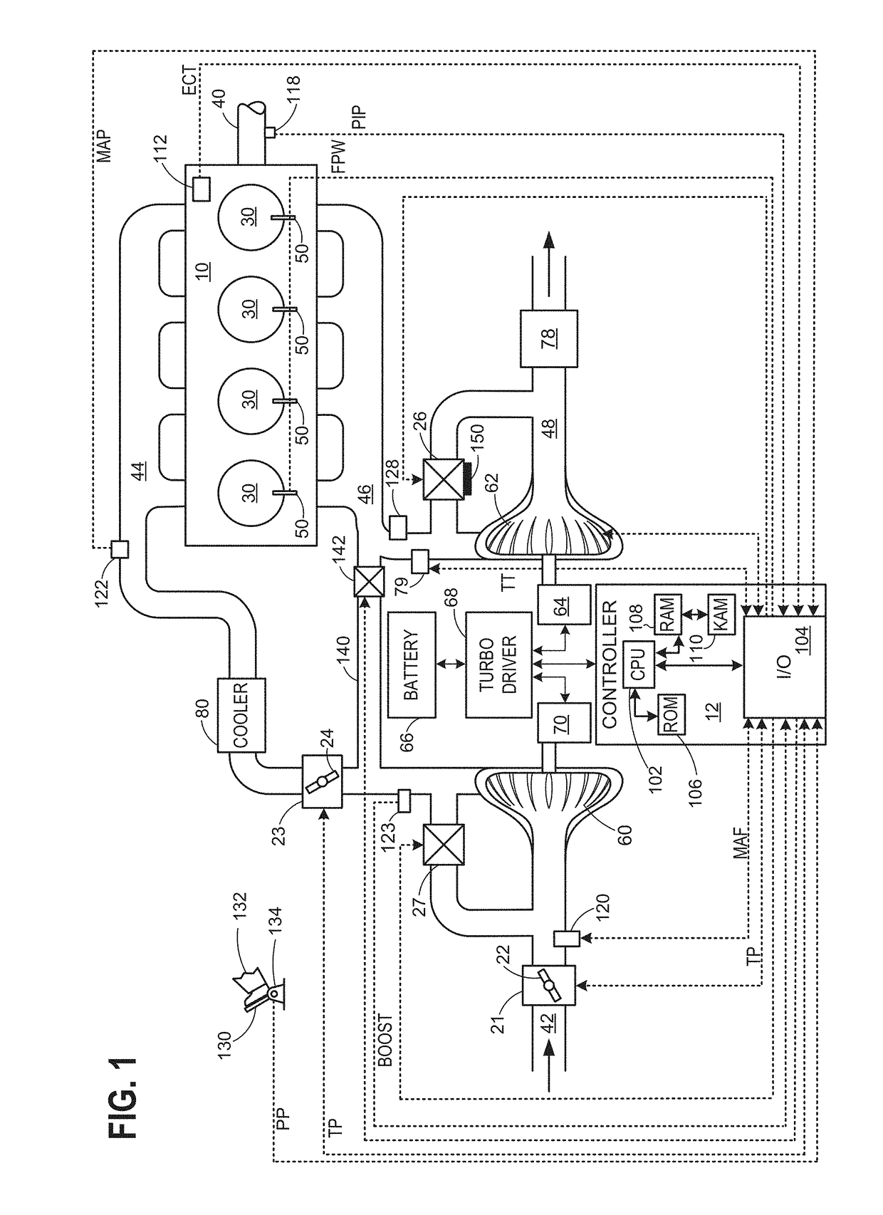
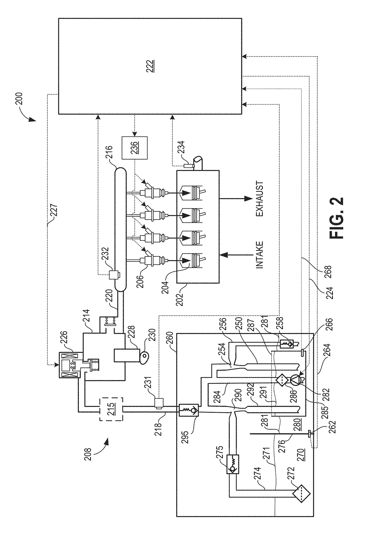
[0018]Methods and systems are provided for increasing robustness of engine operation while maintaining fuel economy by adjusting lift pump pressure operation to maintain jet pump fuel flow and performance in fuel systems shown in FIGS. 1-2. One or more jet pumps, such as the example jet pump in FIG. 4, may be operated in conjunction with a lift pump as shown in the example fuel tank system of FIG. 3, and as is depicted by the example main jet pump that transfers fuel to a main jet pump fuel reservoir in FIG. 5. The influence of lift pump pressure (or voltage) and duty cycle on jet pump flow, and fuel rail pressure and volumetric fuel flow as a function of engine speed, are shown in FIGS. 6 and 7, respectively. A lift pump voltage may be commanded to provide a desired lift pump pressure, as shown in the example timelines of FIGS. 11 and 12. For example, a controller may be configured to execute instructions contained therein, such as the method of FIGS. 8-10, to increase the lift pum...


PUM


Abstract

Methods and systems are provided for increasing a lift pump voltage to a high threshold voltage responsive to a DI pump efficiency being below a threshold efficiency, and increasing a lift pump voltage to a first threshold voltage less than the high threshold voltage responsive to a main jet pump fuel reservoir level being less than a first threshold reservoir level. The approach increases fuel jet pump performance and thereby reducing engine stalls induced by fuel vaporization, while maintaining DI pump efficiency and fuel economy.

Description

FIELD[0001]The field of the disclosure generally relates to fuel systems in internal combustion engines.BACKGROUND AND SUMMARY[0002]Lift pump control systems may be used for a variety of fuel system control purposes. These may include, for example, fuel injection vapor management, injection pressure control, temperature control, and lubrication. In one example, a lift pump supplies fuel to a higher pressure fuel pump (DI pump) that provides a high injection pressure for direct injectors in an internal combustion engine. The DI pump may provide the high injection pressure by supplying high pressure fuel to a fuel rail to which the direct injectors are coupled. A fuel pressure sensor may be disposed in the fuel rail to enable measurement of the fuel rail pressure, on which various aspects of engine operation may be based, such as fuel injection. Furthermore, a lift pump may be operated to apply just enough fuel pressure to the DI pump in order to maintain volumetric efficiency of the ...

Claims


Application Information

Patent Timeline
Patent Type & Authority Patents(United States)
IPC IPC(8): F02D41/38F02D41/30F02D41/20
CPCF02D41/3854F02D41/3082F02D2041/2051F02D2250/02F02D2200/06F02D2200/0614F02D2200/101F02D41/20F02D2041/389
Inventor PURSIFULL, ROSS DYKSTRAWOODRING, CHRISTOPHER ARNOLDULREY, JOSEPH NORMANORD, DAVID
Owner FORD GLOBAL TECH LLC
Why Eureka
Try Eureka