
Heavy duty pressure injection time pressure fuel injection system

a fuel injection system and heavy duty technology, applied in mechanical equipment, machines/engines, electric control, etc., to achieve the effects of reducing diesel fuel consumption, maintaining engine performance and fuel economy, and increasing or decreasing energy conten

Inactive Publication Date: 2013-11-14
BEX AMERICA
View PDF2 Cites 3 Cited by
  • Summary
  • Abstract
  • Description
  • Claims
  • Application Information

AI Technical Summary

Benefits of technology

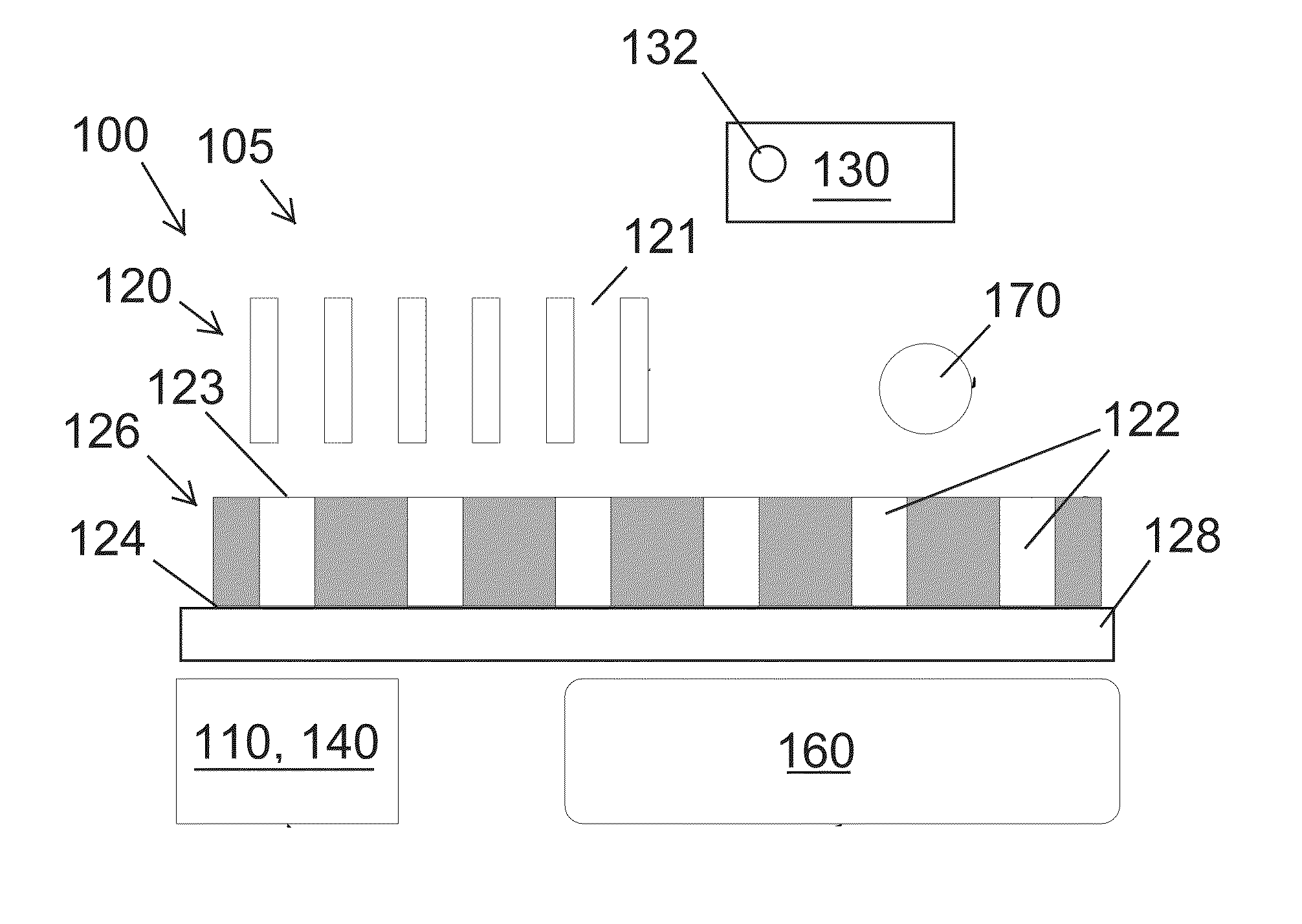
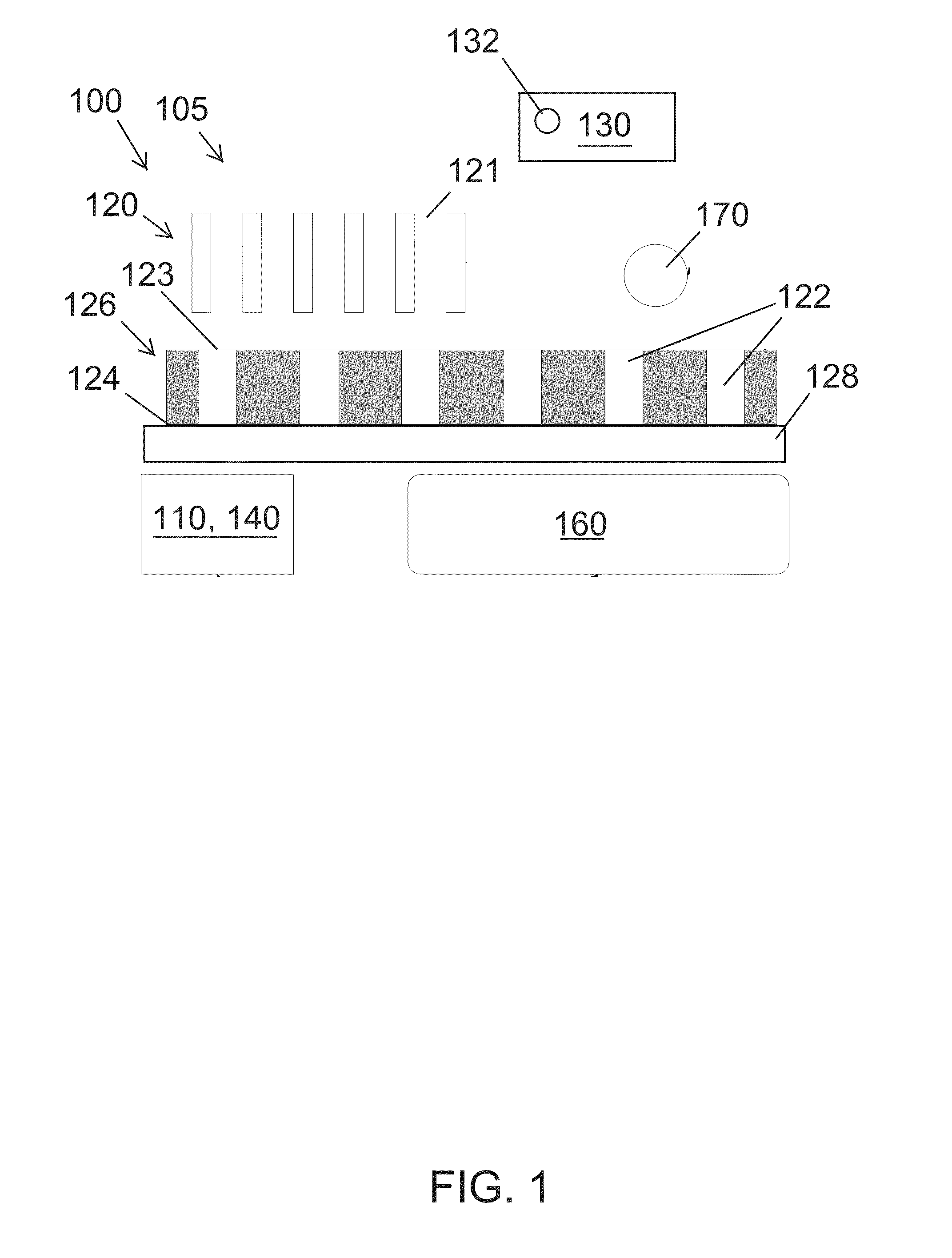
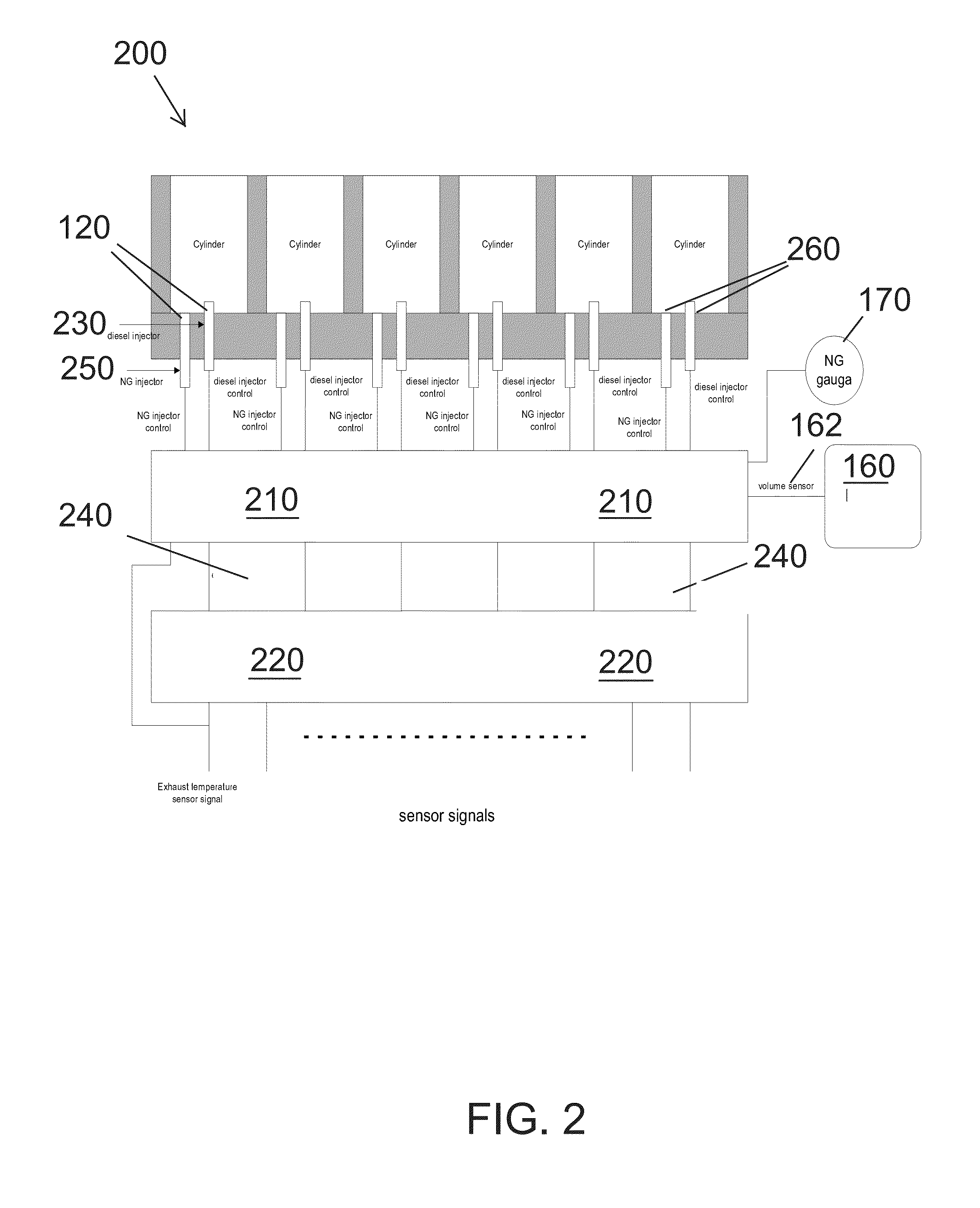
The present invention provides a fuel injection system that can adjust the blending ratio of diesel fuel with gaseous fuel to reduce the amount of diesel fuel consumed. This helps to maintain engine performance and fuel economy by introducing gas with different energy content than diesel fuel.

Problems solved by technology

In practice the lower energy density of gaseous fuels such as CNG or LNG compared to diesel fuel and the differences of air to fuel burn ratios along with differences in molecular structures (i.e., fuel burn rates) are inherent hurdles to blending different fuel types.

Method used


Image

  • Heavy duty pressure injection time pressure fuel injection system
  • Heavy duty pressure injection time pressure fuel injection system
  • Heavy duty pressure injection time pressure fuel injection system

Examples


Embodiment Construction

[0021]Various aspects of the illustrative embodiments will be described using terms commonly employed by those skilled in the art to convey the substance of their work to others skilled in the art. However, it will be apparent to those skilled in the art that the present invention may be practiced with only some of the described aspects. For purposes of explanation, specific numbers, materials and configurations are set forth in order to provide a thorough understanding of the illustrative embodiments. However, it will be apparent to one skilled in the art that the present invention may be practiced without the specific details. In other instances, well-known features are omitted or simplified in order not to obscure the illustrative embodiments.

[0022]Various operations will be described as multiple discrete operations, in turn, in a manner that is most helpful in understanding the present invention however the order of description should not be construed as to imply that these oper...


PUM


Abstract

A fuel injection system that includes an electronic controller that senses engine speed, calculates energy required by an engine existing control unit based upon a signal sent to one or more diesel injection pressure and timing actuators and a plurality of gaseous fuel injectors that respond to commands from the electronic controller and inject gaseous fuel through an injection tube installed in an intake adapter plate fixed between an intake manifold and an engine block. The fuel injection system also includes an on and off switch assembly equipped with a self-diagnostic capability that lights an LED light when a fault in the port injector system is sensed and a blended fuel injector control unit installed between an ECM and a plurality of diesel fuel injectors.

Description

[0001]This application claims priority to U.S. Provisional Application 61 / 646,840 filed on May 14, 2012, the entire disclosure of which is incorporated by reference.BACKGROUND OF THE INVENTION[0002]1. Field of the Invention[0003]The present invention is a diesel-gaseous fuel sequential port injector system. More specifically, the present invention is a heavy duty pressure injection time pressure fuel injection system.[0004]2. Description of the Related Art[0005]In practice the lower energy density of gaseous fuels such as CNG or LNG compared to diesel fuel and the differences of air to fuel burn ratios along with differences in molecular structures (i.e., fuel burn rates) are inherent hurdles to blending different fuel types. The fuel injection system adapts and allows a conventional diesel fueled engine to run on a blend of gaseous fuel in the form of natural gas (i.e., CNG or LNG) and diesel fuel as the primary or pilot fuel. The fuel injection system solves the torque and horsepo...

Claims


Application Information

Patent Timeline
Patent Type & Authority Applications(United States)
IPC IPC(8): F02D41/30
CPCF02D41/30F02D41/221F02D41/0025F02D41/0027F02D2041/2089F02D2041/2093F02D2041/228F02D19/10Y02T10/30
Inventor STROUP, JAMESMO, FENGWEBB, KEN
Owner BEX AMERICA
Learn More