
Inert gas system for floating type oil storage-and-discharge device

An inert gas and floating technology, applied in the field of inert gas system, can solve the problem of limited effect of flue gas volume, and achieve the effect of reducing diesel consumption and environmental pollution

Active Publication Date: 2014-02-19
CHINA NAT OFFSHORE OIL CORP +1
View PDF5 Cites 0 Cited by
  • Summary
  • Abstract
  • Description
  • Claims
  • Application Information

AI Technical Summary

Problems solved by technology

However, this kind of working condition generally only occurs when the thermal oil boiler itself or the entire smoke exhaust system fails and other accidental conditions, and it has limited effect on conventional working conditions where the flue gas volume is insufficient.

Method used


Image

  • Inert gas system for floating type oil storage-and-discharge device

Examples


Embodiment Construction

[0013] The present invention will be described in detail below with reference to the accompanying drawings and embodiments. It should be noted that the present invention can deliver inert gas to multiple oil storage tanks simultaneously, and now only the inert gas delivery to one oil storage tank will be described in detail.

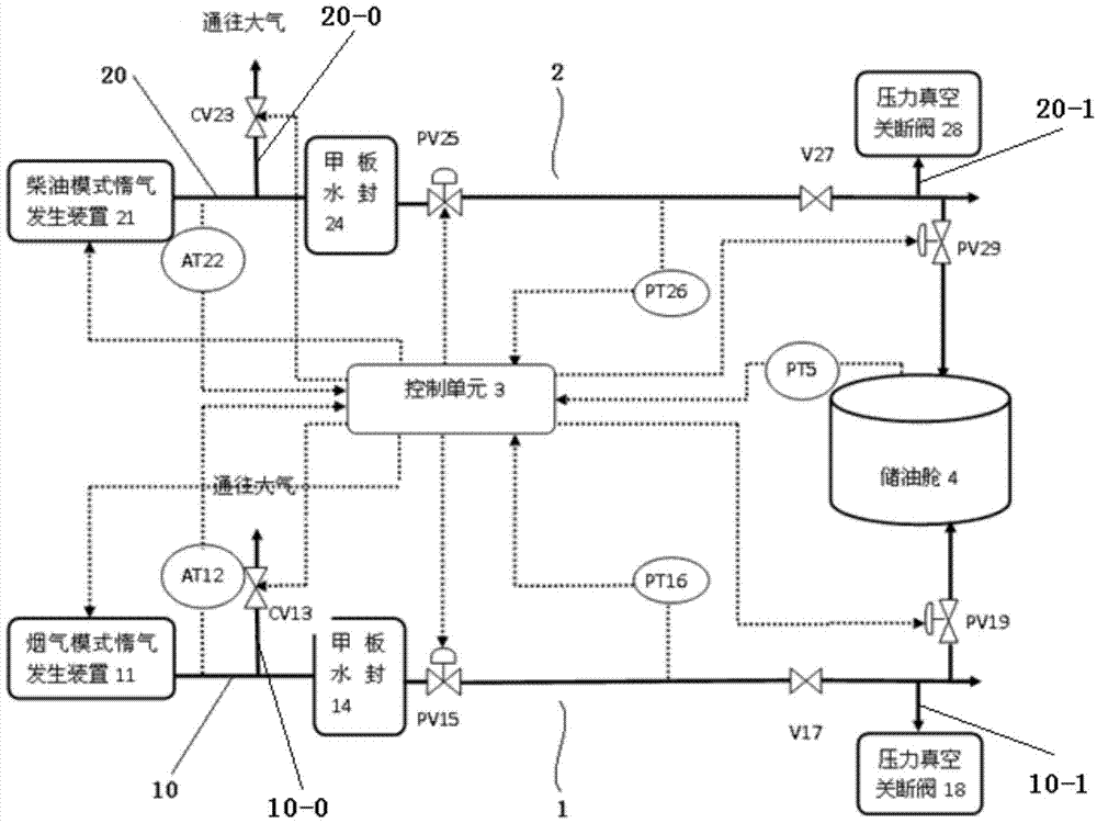
[0014] like figure 1 As shown, the present invention includes a flue gas mode inert gas unit 1 , a diesel mode inert gas unit 2 , a control unit 3 , an oil storage tank 4 and an oil tank pressure transmitter (PT) 5 . Among them, the smoke mode inert gas unit 1 and the diesel mode inert gas unit 2 are independently connected to the oil storage tank 4, and the inert gas pressure signal in the oil storage tank 4 is detected by the oil tank pressure transmitter 5 and transmitted to the control unit 3 , the control unit 3 adjusts the pressure of the oil storage tank 4 according to the inert gas pressure signal.

[0015] The flue gas mode inert gas unit 1 of ...


PUM


Abstract

The invention relates to an inert gas system for a floating type oil storage-and-discharge device. The inert gas system for the floating type oil storage-and-discharge device comprises an exhaust gas and diesel oil mode inert gas unit, a sensor, an oil storage cabin and a control unit. The exhaust gas and diesel oil mode inert gas unit comprises an inert gas main pipe, an exhaust gas and diesel oil mode inert gas generation device, an oxygen analyzer, a deck water seal, a main pipe pressure adjusting valve, a main pipe pressure transmitter, a normally-opened shutoff valve and an oil cabin pressure adjusting valve. The inert gas main pipe communicated with the inert gas generation device is communicated with the oil storage cabin sequentially through the deck water seal, the main pipe pressure adjusting valve, the normally-opened shutoff valve and the oil cabin pressure adjusting valve. The exhaust gas and diesel oil mode inert gas generation device, the main pipe pressure adjusting valve and the oil cabin pressure adjusting valve are respectively and electrically connected with the control unit. The oxygen analyzer and the main pipe pressure transmitter arranged on the inert gas main pip are respectively and electrically connected with the control unit. The inert gas main pipe is provided with two branches, the first branch is communicated with the atmosphere through a control valve electrically connected with the control unit, and the second branch is provided with a pressure vacuum shutoff valve.

Description

technical field [0001] The invention relates to an inert gas system, in particular to a novel inert gas system for a floating oil storage and offloading device. Background technique [0002] The SOLAS Convention of the International Maritime Organization stipulates that an inert gas system should be installed on the floating oil storage and offloading unit (FPSO) where the flash point of crude oil (closed cup test) does not exceed 60°C and that uses crude oil washing operations. The inert gas system is actually a safety protection device to ensure the normal production and export operation of FPSO. The main function of the inert gas is to inert the gas in each oil storage tank and process treatment cabin, so as not to reach the level of supporting combustion. In addition, the inert gas can also make the oil storage tanks and process treatment cabins in a slightly positive pressure state to prevent air from entering, so as to maintain pressure and cover the oil storage tanks...

Claims


Application Information

Patent Timeline
IPC IPC(8): F17D1/02
Inventor 杜佳徐正海徐海波李东亮王春升王建丰李新仲陈荣旗邱里洪毅朱海山何骁勇陈绍凯金丹吴尧增陈卓
Owner CHINA NAT OFFSHORE OIL CORP
Learn More