
Spin dependent tunneling devices having reduced topological coupling

a topological coupling and tunneling device technology, applied in the field of ferromagnetic thin film structures, can solve the problems of no reason to think, inability to bias the free layer to get the optimum sensitivity, and magnetic material layer magnetostatic coupling between the layers of magnetic materials

Inactive Publication Date: 2008-06-24
NVE CORP
View PDF26 Cites 20 Cited by
  • Summary
  • Abstract
  • Description
  • Claims
  • Application Information

AI Technical Summary

Benefits of technology

[0040]So far, only two ferromagnetic surfaces have been included in the calculation because the assumption has been made that the outer ferromagnetic surfaces are very far away to the point where the magnetic intereactions with those surfaces are negligible, or that the other surfaces have no roughness (a

Problems solved by technology

This surface roughness can lead to magnetostatic coupling between magnetic material layers.
However, there is no reason to think that the grain structure looks any different going along different orthogonal directions, i.e. the x or y directions.
There are undesirable effects of such orange peel coupling on the behavior of various magnetic material layer devices in which this coupling occurs.
This makes it impossible to bias the free layer to get optimum sensitivity as both portions cannot be biased equally.

Method used


Image

  • Spin dependent tunneling devices having reduced topological coupling
  • Spin dependent tunneling devices having reduced topological coupling
  • Spin dependent tunneling devices having reduced topological coupling

Examples


Embodiment Construction

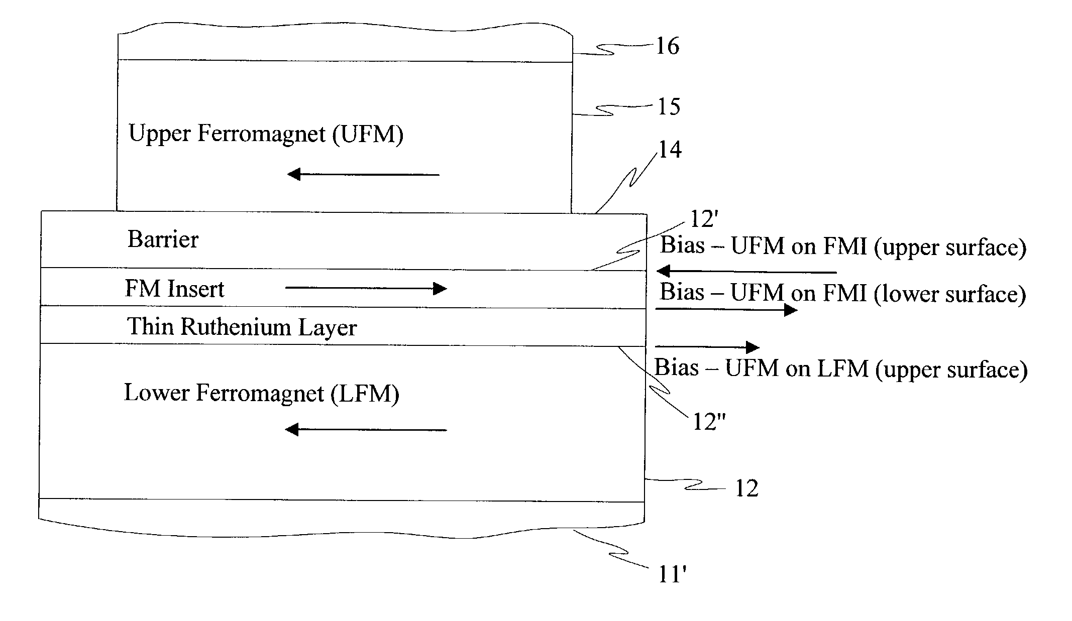
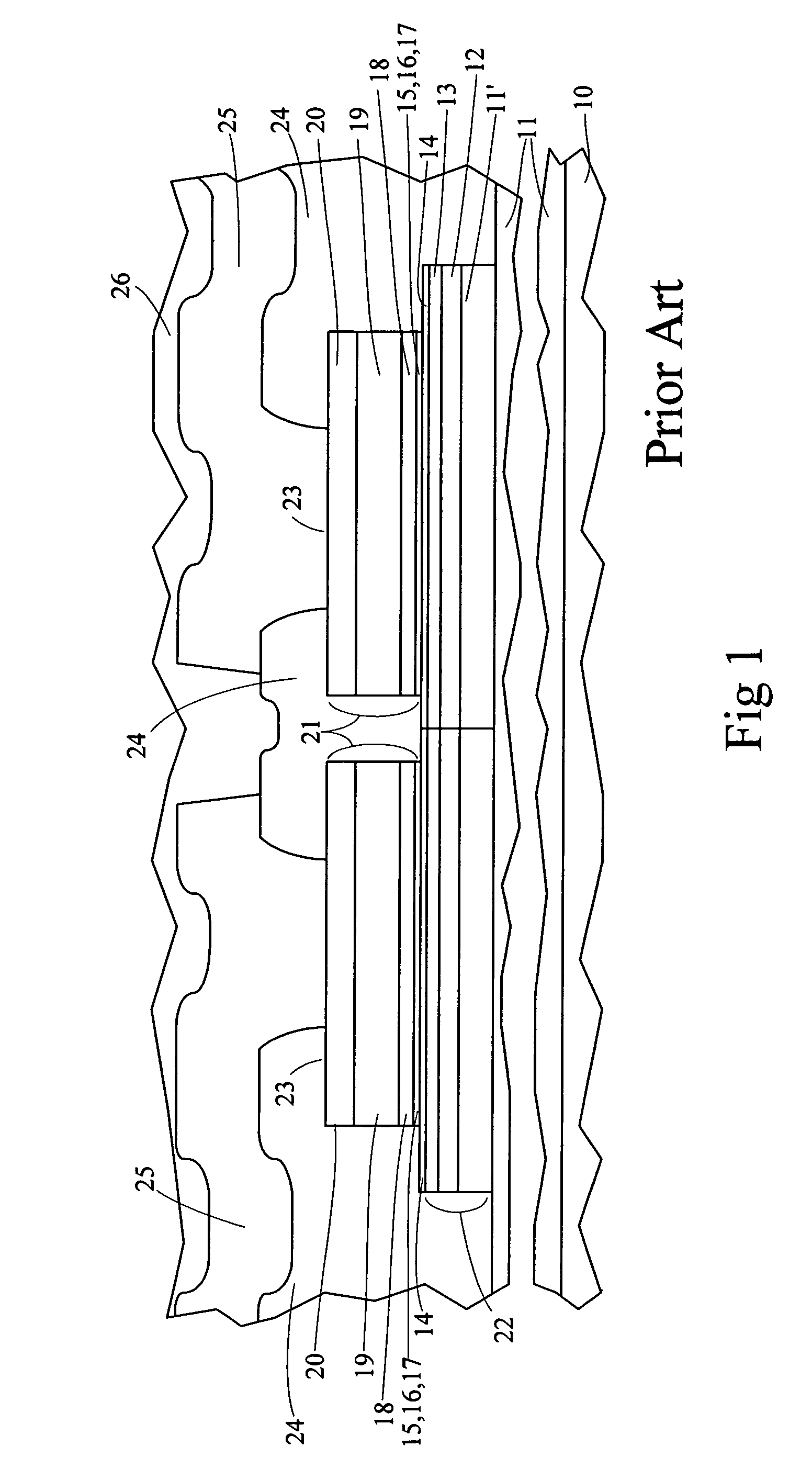
[0061]A spin dependent tunneling sensing device is represented in the layer stack representation diagram of FIG. 4A with broken away electrodes as indicated by wavy lines. In this diagram, which is closely associated with the layer diagram of FIG. 1 (as indicated through use of the same numerical designations for comparable portions in each) and with the layer schematic of FIG. 3C, there is a several Oe coupling field between the bottom surface of ferromagnetic layer 15 above tunneling barrier 14 and the top surface of ferromagnetic layer 12 below that barrier. Layer magnetization direction possibilities are indicated by arrows in the corresponding ferromagnetic layer. Ferromagnetic layer 15 above barrier 14 is part of a pinned synthetic antiferromagnet (SAF), and the coupling field emanating therefrom is applied, effectively, as a constant field on ferromagnetic layer 12 under barrier 14. As described above, the origin of the coupling field is believed to be the spatially correlate...


PUM


Abstract

A ferromagnetic thin-film based magnetic device with internal film coupling compensation including a nonmagnetic material intermediate layer with an initial thin-film of an anisotropic ferromagnetic material on one side. A compensation thin-film of an anisotropic ferromagnetic material is provided on the opposite side with an antiparallel coupling layer thereon and a subsequent thin-film of an anisotropic ferromagnetic material on the antiparallel coupling layer with the compensation thin-film being less thick than the subsequent thin-film. A antiferromagnetic layer can be supported by the layers on either side of the intermediate layer.

Description

CROSS-REFERENCE TO RELATED APPLICATION(S)[0001]This application claims the benefit of Provisional Application No. 60 / 368,172 filed Mar. 27, 2002 for “SPIN DEPENDENT TUNNELING DEVICES HAVING ORANGE PEEL COUPLING REDUCTION STRUCTURES”.BACKGROUND OF THE INVENTION[0002]The present invention relates to ferromagnetic thin-film structures and, more particularly, to ferromagnetic thin-film structures exhibiting relatively large magnetoresistive characteristics.[0003]Many kinds of electronic systems make use of magnetic material based devices. Digital memories are used extensively in digital systems of many kinds including computers and computer systems components, and digital signal processing systems. Such memories can be advantageously based on the storage of digital bits as alternative states of magnetization in magnetic materials in each memory cell, particularly in cells using thin-film magnetic materials, resulting in memories which use less electrical power and do not lose informatio...

Claims


Application Information

Patent Timeline
IPC IPC(8): G11B5/39G11B5/127G01R33/09H01L43/08
CPCB82Y25/00G01R33/093H01L43/08Y10T428/1121Y10T428/1129Y10T428/1143Y10T428/1193Y10T428/31504H10N50/10
Inventor DAUGHTON, JAMES M.WANG, DEXIN
Owner NVE CORP
Learn More