Directional antenna

a technology of directional antennas and antenna details, applied in the direction of antennas, antenna details, basic electric elements, etc., can solve the problems of eventual material failure and wind load problems

Inactive Publication Date: 2008-06-24
THOMAS HAROLD J
View PDF10 Cites 0 Cited by
  • Summary
  • Abstract
  • Description
  • Claims
  • Application Information

AI Technical Summary

Benefits of technology

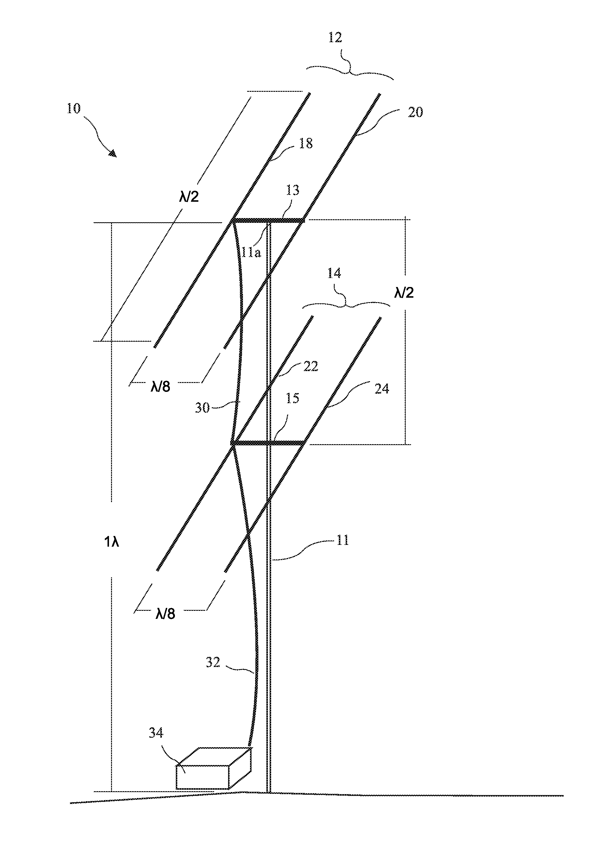
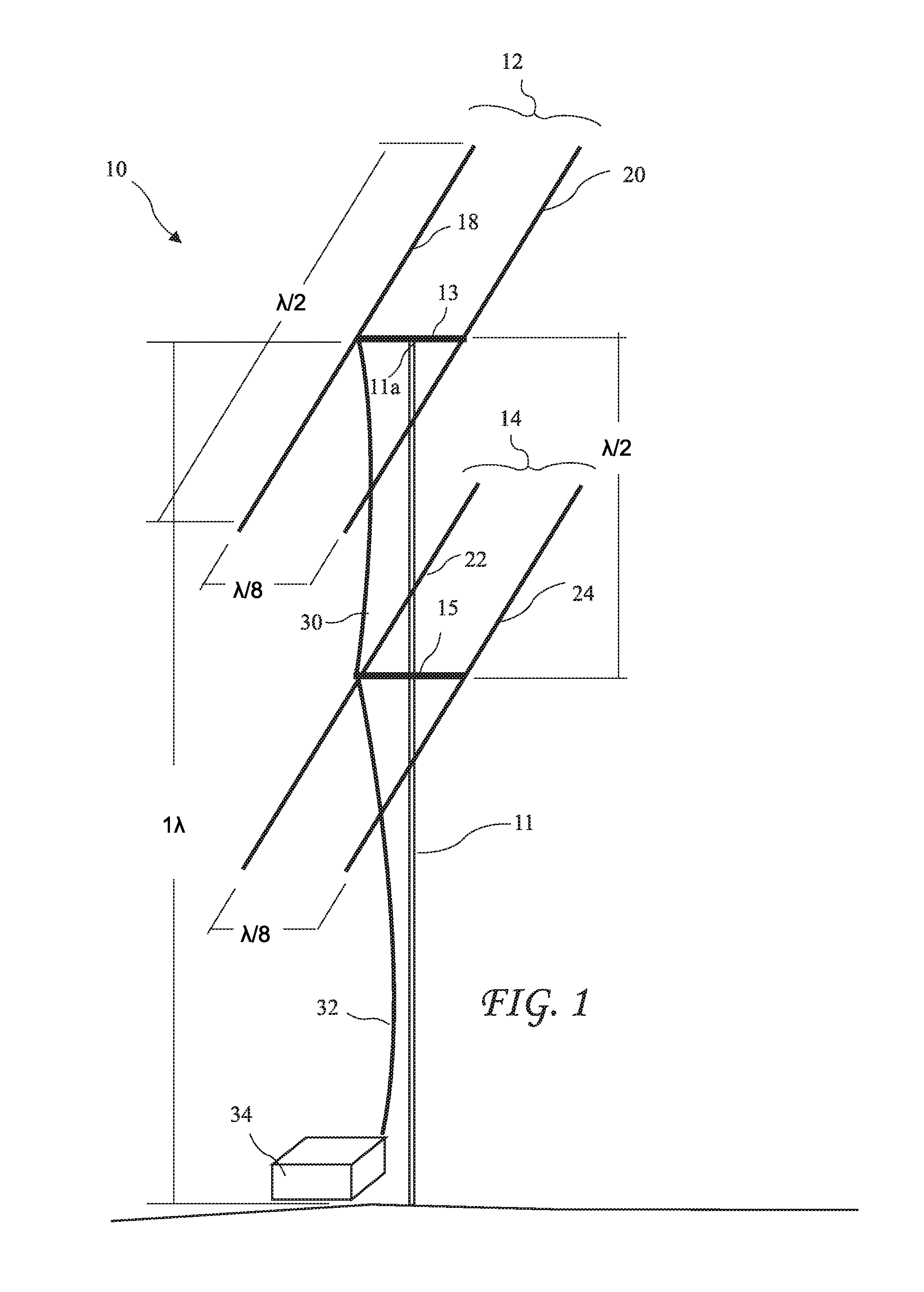
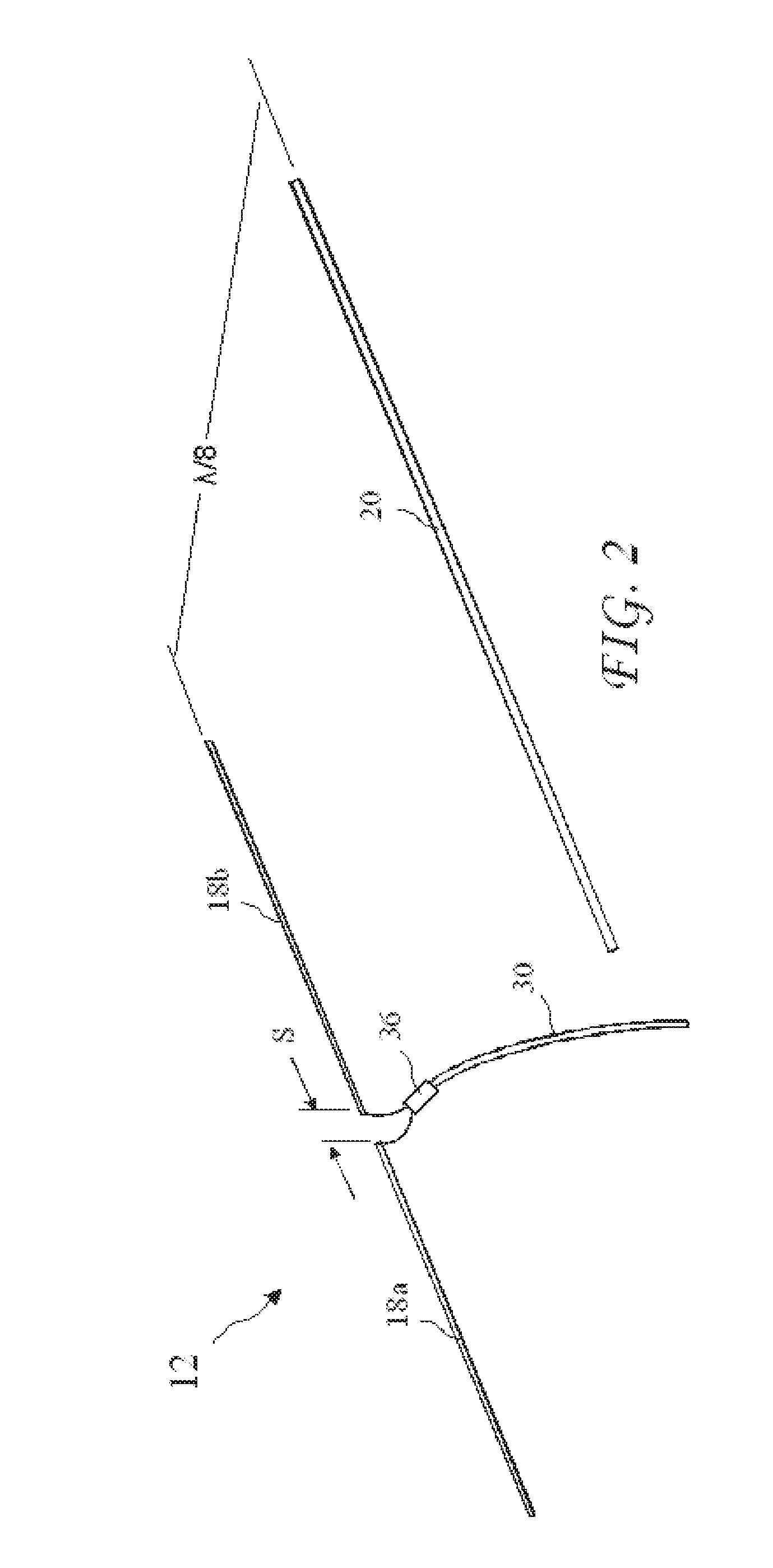
[0006]In accordance with one aspect of the invention, there is provided an antenna array including a vertical mast approximately one wavelength high and including a top, a horizontal upper beam attached to the vertical mast proximal to the top, a lower beam attached to the vertical mast approximately one half wavelength below the upper beam, an upper antenna supported by the upper beam, and a lower antenna supported by the lower beam. The upper antenna includes an upper driven dipole element having a length of approximately one half wavelength, and an upper directing element having a length of approximately one half wavelength and horizontally spaced apart approximately one eighth wavelength from the upper driven dipole element and approximately parallel to the upper driven dipole element. The lower antenna includes a lower driven dipole element having a length of approximately one half wavelength, and a lower directing element having a length of approximately one half wavelength and horizontally spaced apart approximately one eighth wavelength from the lower driven dipole element and approximately parallel to the lower driven dipole element. A first transmission line is approximately one half wavelength in length and electrically connects the upper driven dipole element to the lower driven dipole element. A second transmission line has a length of an integer multiple of one half wavelength and electrically connects the top and bottom driven dipole elements to a transmitter and a receiver.
[0007]In accordance with one aspect of the invention, there is prov

Problems solved by technology

A large antenna is also susceptible to wind loading (which could lead to eventual material failure).
While the antenna of the '784 patent achieves some improvement over previous antennas, it also creates wind load issues and even greater improvements are desired.

Method used


Image

  • Directional antenna
  • Directional antenna
  • Directional antenna

Examples


Embodiment Construction

[0013]The following description is of the best mode presently contemplated for carrying out the invention. This description is not to be taken in a limiting sense, but is made merely for the purpose of describing one or more preferred embodiments of the invention. The scope of the invention should be determined with reference to the claims.

[0014]A detailed perspective view of an antenna array 10 according to the present invention is shown in FIG. 1. The antenna array 10 includes an approximately vertical support (or mast) 11 having a top 11a and supporting an approximately horizontal upper beam 13 residing proximal to said top 11a and an approximately horizontal lower beam 15. Both the upper beam 13 and the lower beam 15 are preferably connected to the mast 11 at the midpoints of the beams 13 and 15 to provide a neutral mechanical balance. Upper beam 13 supports an upper antenna 12 comprising an upper driven element 18 and an upper directing element 20. The lower beam 15 supports a ...


PUM


Abstract

An antenna array includes an upper antenna and a lower antenna. Each antenna includes a driver dipole element and a director element horizontally spaced apart approximately one eighth wavelength from the driver dipole element. The driver dipole element is preferably approximately one half wavelength in overall length and the director element is preferably one half wavelength in length. The upper antenna is vertically spaced above the ground by approximately one wavelength and the upper and lower antennas are vertically spaced approximately one half wavelength apart. A preferred use of the antenna array is as an amateur radio antenna and a preferred frequency band is 14.0 to 14.350 MHZ corresponding to an approximately 20 meter wavelength.

Description

BACKGROUND OF THE INVENTION[0001]The present invention relates to a directional antenna and in particular, the spacing between the radiating and directing elements of the antenna.[0002]In some radio communication applications, a radio operator finds it mandatory to communicate with a distant station located in a particular direction. This is particularly important for a radio operator when: a distant station is difficult to hear, the distant station cannot hear the radio operator, or the radio operator wishes to reduce adjacent station interference from another station located in a different direction than the distant station. To accomplish this task, directional antennas are used. Directional antennas are used to boost the effective transmitted radiated power and increase the receiving sensitivity of a station to other stations in a desired direction. Current solutions are found in multi-element antennas (such as a Yagi or a Quad). These antennas generally contain elements which ar...

Claims


Application Information

Patent Timeline
IPC IPC(8): H01Q21/12
CPCH01Q19/30H01Q21/28
Inventor THOMAS, HAROLD J.
Owner THOMAS HAROLD J
Why Eureka
Try Eureka