Thin film magnetic head and magnetic recording apparatus with partitioned heat sink layer

a magnetic recording and partitioning technology, applied in the direction of maintaining head carrier alignment, recording information storage, instruments, etc., can solve the problem of reducing the likelihood of the write shield layer expanding thermally, and achieve the effect of reducing the amount of protruding write shield layer, preventing a collision with the recording medium, and ensuring a recording operation with stability

Active Publication Date: 2008-06-24
TDK CORPARATION +1
View PDF13 Cites 33 Cited by
  • Summary
  • Abstract
  • Description
  • Claims
  • Application Information

AI Technical Summary

Benefits of technology

[0009]The invention is designed to overcome the foregoing problems. It is a first object of the invention to provide a thin film magnetic head which is capable of reducing the amount of protrusion of a write shield layer, thereby preventing a collision with a recording medium, and thereby ensuring a recording operation with stability.
[0010]It is a second object of the invention to provide a magnetic recording apparatus equipped with a thin film magnetic head of the invention, which is capable of preventing the occurrence of a breakdown resulting from a collision of the thin film magnetic head with a recording medium.
[0011]A thin film magnetic head of the invention, which performs magnetic processing on a recording medium which moves in a medium travel direction, includes a thin film coil which generates a magnetic flux; a magnetic pole layer which emits the magnetic flux generated by the thin film coil to the recording medium, the magnetic pole layer being located on the side, of the thin film coil, opposite to the medium travel direction, the magnetic pole layer extending rearward from a recording-medium-facing surface to be faced with the recording medium; a write shield layer which prevents divergence of the magnetic flux emitted from the magnetic pole layer, the write shield layer being located on the medium-travel-direction side of the thin film coil and extending rearward from the recording-medium-facing surface; and a heat sink layer which dissipates heat produced by the thin film coil, the heat sink layer being located on the side, of the thin film coil, opposite to the medium travel direction.

Problems solved by technology

As a result, the thin film magnetic head of the invention reduces the likelihood of the heat accumulating in the write shield layer located on the medium-travel-direction side of the thin film coil, and thus reduces the likelihood of the write shield layer expanding thermally.

Method used


Image

  • Thin film magnetic head and magnetic recording apparatus with partitioned heat sink layer
  • Thin film magnetic head and magnetic recording apparatus with partitioned heat sink layer
  • Thin film magnetic head and magnetic recording apparatus with partitioned heat sink layer

Examples


first embodiment

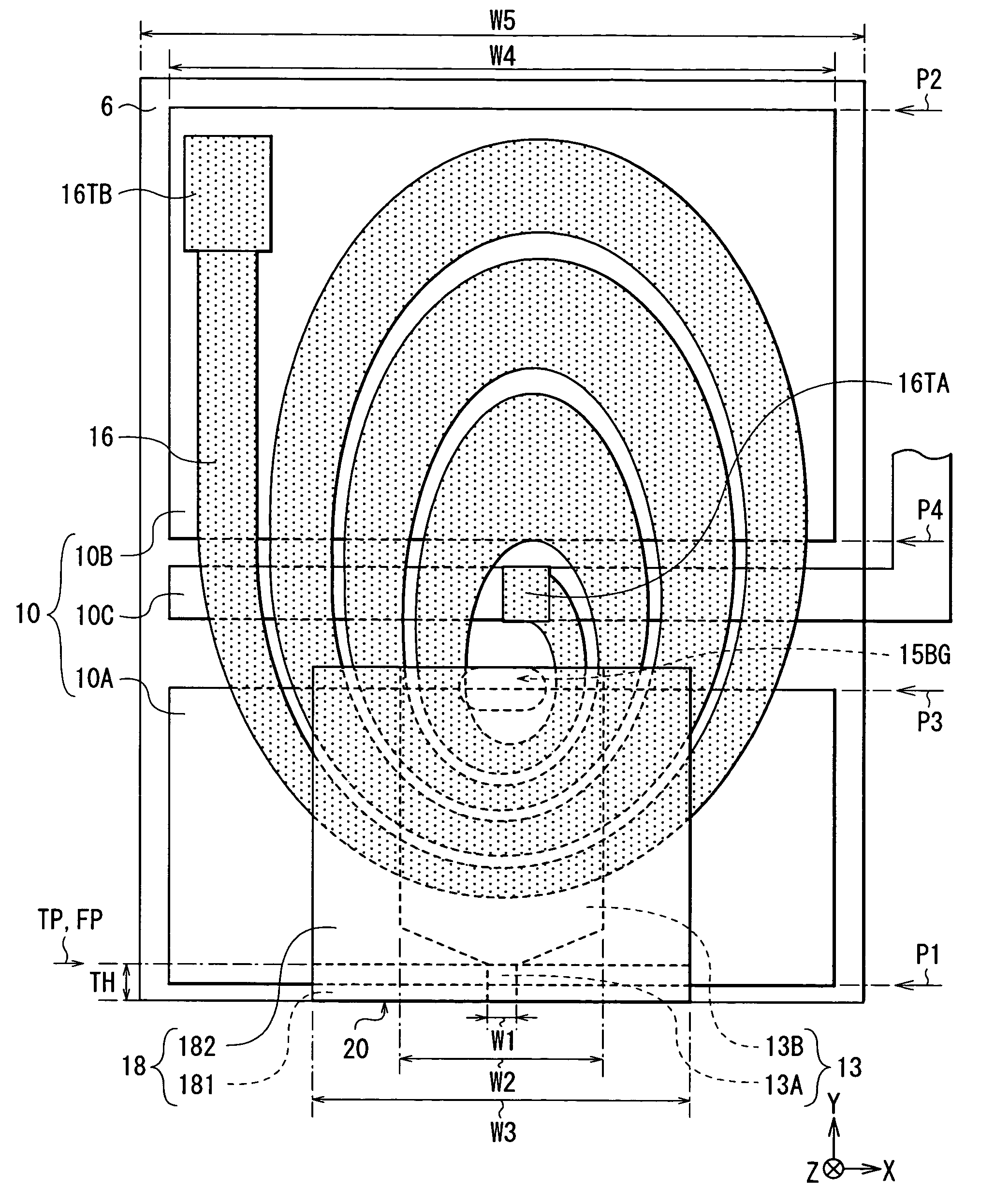
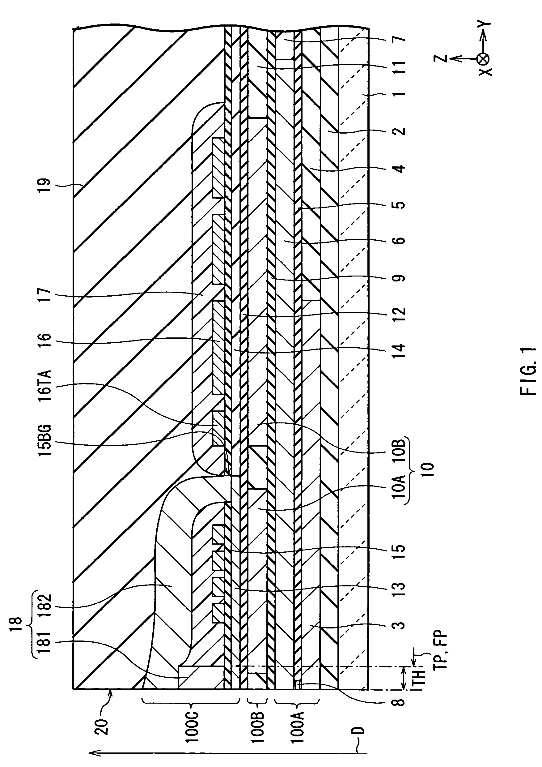
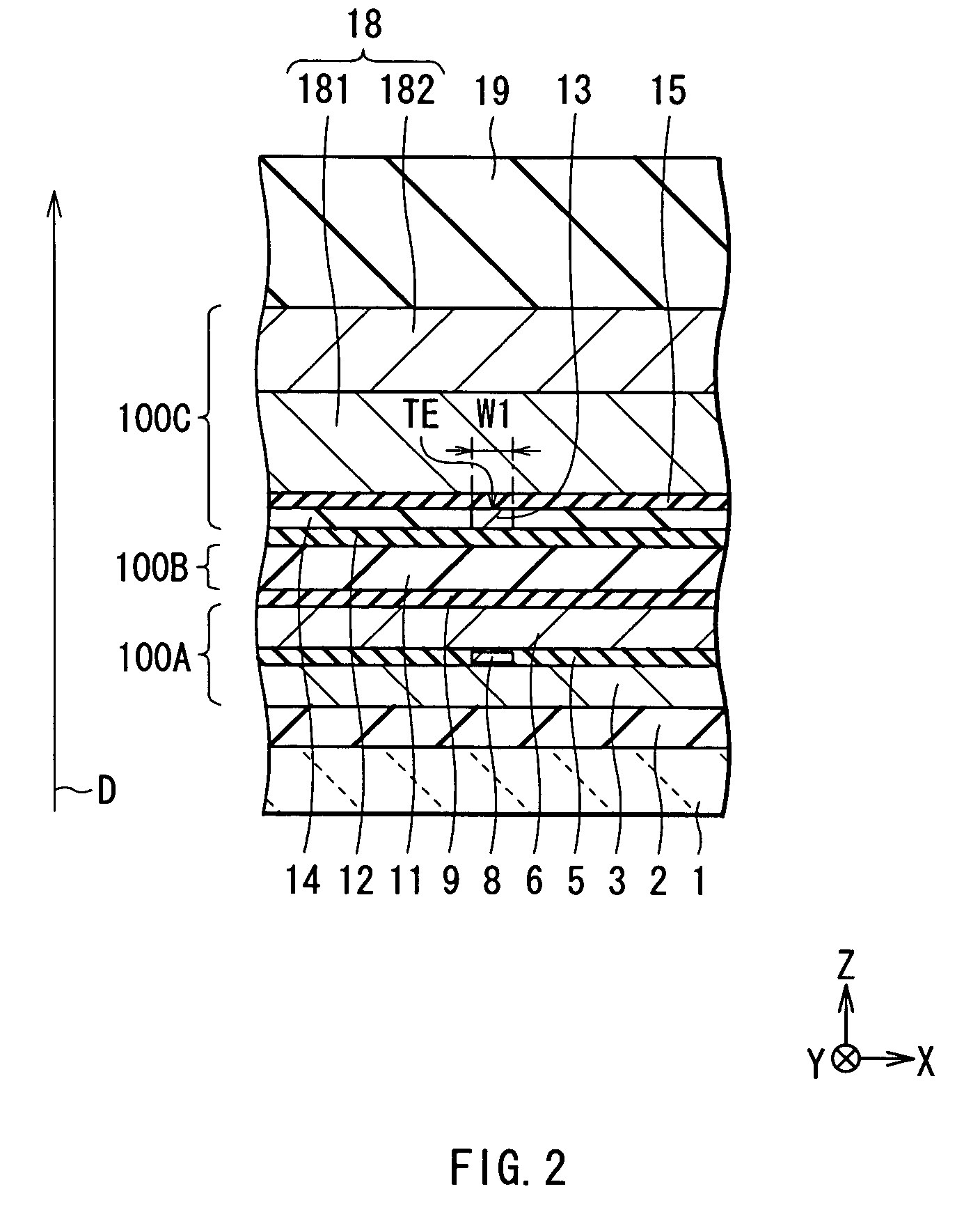
[0042]Firstly, the description is given with reference to FIGS. 1 to 3 with regard to the configuration of a thin film magnetic head according to a first embodiment of the invention. FIGS. 1 and 2 show the cross-sectional configuration of the thin film magnetic head, and FIGS. 1 and 2 show a cross section perpendicular to an air bearing surface (i.e., a cross section along the Y-Z plane) and a cross section parallel to the air bearing surface (i.e., a cross section along the X-Z plane), respectively. FIG. 3 shows the plan configuration of a principal part of the thin film magnetic head shown in FIGS. 1 and 2. Incidentally, the upward-pointing arrow D shown in FIGS. 1 and 2 indicates a direction in which a magnetic recording medium (not shown) travels relative to the thin film magnetic head (i.e., a medium travel direction).

[0043]Hereinafter, dimensions along the X, Y and Z axes shown in FIGS. 1 to 3 are defined as a “width”, a “length”, and a “thickness”, respectively. The side clos...

second embodiment

[0102]Next, the description is given with regard to a second embodiment of the invention.

[0103]FIGS. 19 and 20 show the configuration of a thin film magnetic head according to the second embodiment of the invention. FIG. 19 shows the cross-sectional configuration corresponding to FIG. 1, and FIG. 20 shows the plan configuration corresponding to FIG. 3. In FIGS. 19 and 20, the same structural components as the components discussed in the description of the above-mentioned first embodiment are indicated by the same reference numerals.

[0104]The thin film magnetic head according to the second embodiment has the same configuration as the thin film magnetic head according to the above-mentioned first embodiment, except for the configuration of the heat sink layer 10. Specifically, the heat sink layer 10 of the second embodiment is partitioned into three portions (i.e., the frontward portion 10A, an intermediate portion 10C, and the rearward portion 10B) in the direction in which the heat ...

examples

[0117]Next, the description is given with regard to an example of the invention.

[0118]Recording was performed using the magnetic recording apparatus (see FIGS. 21 and 22) equipped with the thin film magnetic head of the above-described first embodiment (see FIGS. 1 to 3) (hereinafter referred to simply as “the thin film magnetic head of the invention”), which was used as a typical representative of the thin film magnetic heads of the invention having the configurations discussed in the description of the above-mentioned embodiments. During the recording, the measurement was made of the amount of protrusion of the thin film magnetic head of the invention. The results of measurement are shown in FIG. 23. FIG. 23 shows the correlation between the head position and the amount of protrusion. In FIG. 23, the “horizontal axis” indicates the head position. As employed herein, the head position refers to the position (μm) relative to a reference position (0 μm) as viewed along the thickness ...


PUM

PropertyMeasurementUnit
thicknessaaaaaaaaaa
widthaaaaaaaaaa
thicknessaaaaaaaaaa

Abstract

Provided is a thin film magnetic head capable of reducing the amount of protrusion of a write shield layer, thereby preventing a collision with a recording medium, and thereby ensuring a recording operation with stability. A heat sink layer is disposed on the leading side of a thin film coil in order to dissipate heat produced by the thin film coil. When the thin film coil produces heat during the recording of information, priority is given to the guidance of the heat to the leading side of the thin film coil, namely, the side opposite to the position of the write shield layer, rather than the guidance of the heat to the trailing side of the thin film coil, namely, the position of the write shield layer, so as to dissipate the heat. Thus, the thin film magnetic head reduces the likelihood of the heat accumulating in the write shield layer, thus reduces the likelihood of the write shield layer expanding thermally, and thus reduces the amount of protrusion of the write shield layer.

Description

BACKGROUND OF THE INVENTION[0001]1. Field of the Invention[0002]The invention relates to a thin film magnetic head including an inductive magnetic transducer for use in at least recording, and a magnetic recording apparatus equipped with a thin film magnetic head.[0003]2. Description of the Related Art[0004]Recently, an improvement in performance of a thin film magnetic head mounted on a magnetic recording apparatus (e.g., a hard disk drive) has been sought in accordance with an increase in a surface recording density of a magnetic recording medium (e.g., a hard disk). A longitudinal recording type and a perpendicular recording type, for example, are known as the recording types of the thin film magnetic head. The longitudinal recording type is designed to orient a signal magnetic field in the in-plane direction of the hard disk (i.e., the longitudinal direction thereof). The perpendicular recording type is designed to orient a signal magnetic field in a direction perpendicular to t...

Claims


Application Information

Patent Timeline
Patent Type & Authority Patents(United States)
IPC IPC(8): G11B5/40G11B5/127G11B5/31G11B5/17G11B5/39G11B5/60
CPCG11B5/127G11B5/17G11B5/3133G11B5/3136G11B5/6005G11B5/3116G11B5/3123
Inventor MATONO, NAOTOOTA, NORIKAZUOTSUKI, MITSUO
Owner TDK CORPARATION
Why Eureka
Try Eureka