Sunshade panel apparatus

a technology of sunshade panels and sunshade panels, which is applied in the direction of roofs, superstructure subunits, vehicle components, etc., can solve the problem of increasing the driving force of the sunshade panels to achieve the effect of sliding the sunshade panels

Inactive Publication Date: 2008-07-01
AISIN SEIKI KK
View PDF5 Cites 7 Cited by
  • Summary
  • Abstract
  • Description
  • Claims
  • Application Information

AI Technical Summary

Benefits of technology

[0078]According to the embodiments, the supporting shaft, the engagement shaft and the shaft of the connecting member are formed by bending the connecting link member into the shape of substantially letter S. Therefore, the connecting member can be structured easily at low cost.

Problems solved by technology

Thus, the resistance when sliding the sunshade panels becomes large, which brings a drawback that the drive force is required to be increased for sliding the sunshade panels.

Method used


Image

  • Sunshade panel apparatus
  • Sunshade panel apparatus
  • Sunshade panel apparatus

Examples


first embodiment

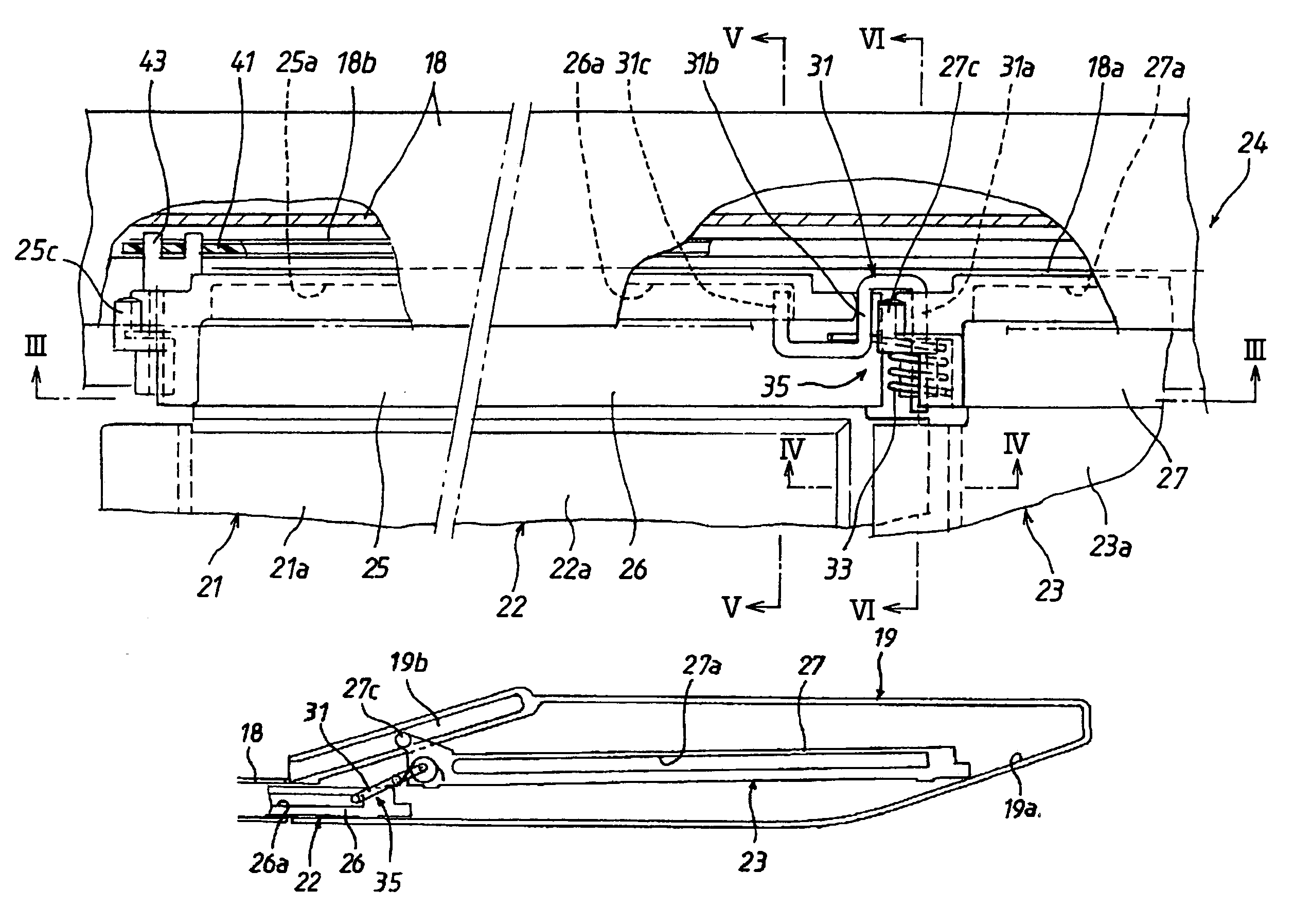
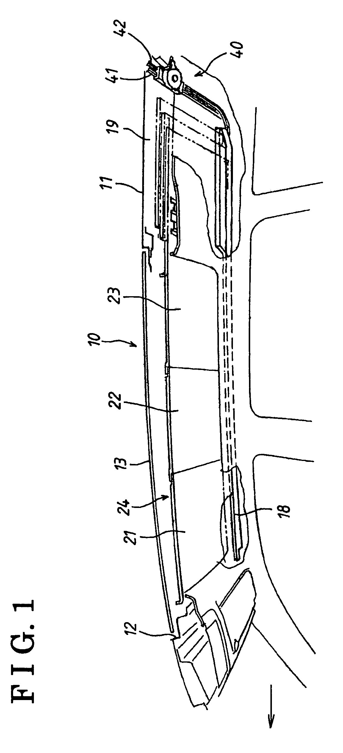
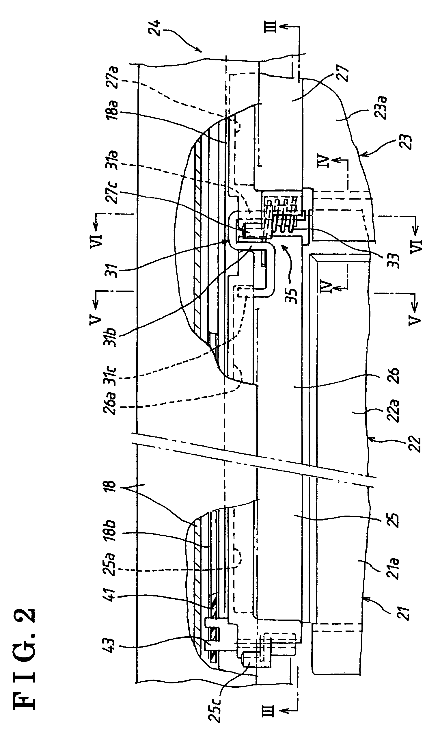
[0026]the present invention will be explained referring to FIGS. 1-8. FIG. 1 shows a state where a sunroof apparatus 10 provided at a roof portion 11 of a vehicle is sectioned at the central portion in a width direction of the vehicle. A direction indicated with an arrow is a forward direction of the vehicle. On the roof portion 11 of the vehicle, an opening 12 is formed. A panel 13 made from a transparent glass plate is mounted to the opening 12 so that sunlight passes through the panel 13 into a vehicle compartment. Below the panel 13, a sunshade panel apparatus 24 is provided in order to adjust light shading, which includes plural (e.g., three) sunshade panels 21, 22 and 23. The sunshade panel 21 is also mentioned as a first sunshade panel 21 provided at forefront in a forward and a backward direction of the vehicle within the sunshade panel apparatus 24, the sunshade panel 22 is also mentioned as a second sunshade panel 22 interposed the sunshade panel 21 and the sunshade panel ...

second embodiment

[0060]In the second embodiment, the connection link member 31 is attached to the forward sides or ends of two adjacent sunshade panels as viewed from the closing direction. Therefore, there is virtually no need of providing an engagement groove 25a and an engagement portion 25b at the foremost (first) sunshade panel 21.

[0061]In the second embodiment as well, as is the case of the first embodiment, in the state where the sunshade panels 21, 22, 23 are closed, when the foremost (first) sunshade panel 21 is driven by the drive unit 40 to be pulled rearward in the storage direction (in the opening direction), the plurality of sunshade panels 21, 22, 23 are integrally slid rearward along the guide rails 18, so that the rearmost (third) sunshade panel 23 is stored into the panel housing portion 19 (see FIG. 11(A)).

[0062]When the rearmost sunshade panel 23 is pulled within the panel housing portion 19 in a predetermined amount, the rear end portion thereof runs onto the slant guide surface...


PUM


Abstract

A sunshade panel apparatus includes a first sunshade panel, a second sunshade panel and a third sunshade panel a first connecting mechanism connecting the second sunshade panel and the third sunshade panel so that the second sunshade panel and the third sunshade panel are moved integrally or relatively; a guide rail supporting the first, second and third sunshade panels to be slidable within the same plane; and a panel housing portion for storing the first, second and third sunshade panels overlapping one another in parallel and provided with inclined guiding portions to move the first, second and third sunshade panels in parallel in an upward direction of the vehicle, wherein the first connecting mechanism has a supporting portion, an engagement groove, an engagement portion; and a biasing member.

Description

CROSS REFERENCE TO RELATED APPLICATIONS[0001]This application is based on and claims priority under 35 U.S.C. §119 with respect to Japanese Patent Application No. 2005-348411 filed on Dec. 1, 2005, the entire content of which is incorporated herein by reference.FIELD OF THE INVENTION[0002]The present invention relates to a sunshade panel apparatus. More particularly, the present invention pertains to a sunshade panel apparatus including a plurality of sunshade panels which can be opened and closed.BACKGROUND[0003]In sunroof apparatuses formed with an opening on the roof of a vehicle, a fixed panel or a movable panel including a transparent glass plate is provided at the opening on the roof. In order to adjust the amount of the sunlight taken through the panel into a vehicle compartment, a known sunshade panel apparatus disclosed in, for example, JP2003-48433A is employed.[0004]With the construction of the sunshade panel apparatus described in JP2003-48433A (i.e., paragraphs [0029], ...

Claims


Application Information

Patent Timeline
Patent Type & Authority Patents(United States)
IPC IPC(8): B60J7/00
CPCB60J7/0038
Inventor MORI, KEIJI
Owner AISIN SEIKI KK
Why Eureka
Try Eureka