Planar light source device and display device using the same

a technology of light source device and display device, which is applied in the direction of static indicating device, lighting and heating apparatus, instruments, etc., can solve the problems of increasing the cost of the planar light source device itself, white balance, and increasing the manufacturing cos

Inactive Publication Date: 2008-07-01
MITSUBISHI ELECTRIC CORP
View PDF14 Cites 18 Cited by
  • Summary
  • Abstract
  • Description
  • Claims
  • Application Information

AI Technical Summary

Benefits of technology

[0009]It is an object of the present invention to provide a planar light source device capable of obtaining stabilized quantities of light emission of light emitting diodes without having to use a particular optical sensor, and a display device using the same.
[0011]In this planar light source device, the light emitting diodes being turned off detect the quantities of light from the other said light emitting diodes, and adjust the quantities of light emission of the other said light emitting diodes based on the detected quantities of light. This attains stabilized quantities of light emission of the light emitting diodes without having to use a particular optical sensor, to thereby realize a planar light source device having stabilized luminance and chromaticity.

Problems solved by technology

Accordingly, a problem is encountered in the emission of white light by using LEDs of the three colors R, G and B such that a white balance varies with a change in ambient temperature.
However, the provision of an additional particular optical sensor for a planar light source device involves increases in component count and the number of steps of the device, increasing the manufacturing cost.
Further, the addition of an optical sensor, which is expensive in itself, increases the cost for the planar light source device itself.

Method used


Image

  • Planar light source device and display device using the same
  • Planar light source device and display device using the same
  • Planar light source device and display device using the same

Examples


first preferred embodiment

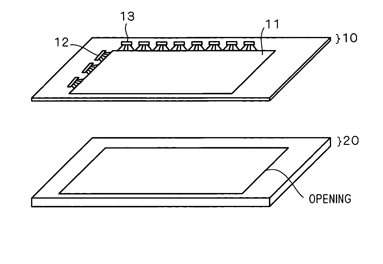
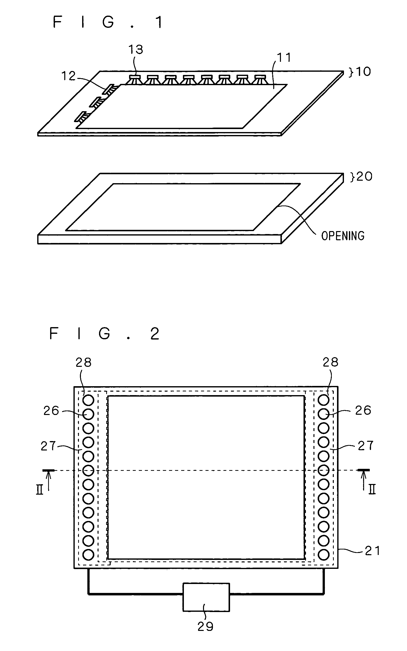
[0024]A first preferred embodiment of the present invention will be described based on an embodiment using a planar light source device as a backlight of a liquid crystal display device. Yet a planar light source device according to the present invention is not restricted to this embodiment. FIG. 1 is an exploded perspective view illustrating the structure of a liquid crystal display device according to the first preferred embodiment. This liquid crystal display device includes a liquid crystal display panel 10 writing a desired image to pixels for display, and a backlight 20 irradiating light from the back of the liquid crystal display panel 10. A liquid crystal is held between the liquid crystal display panel 10 and an opposed substrate 11, and TFTs (thin film transistors) are formed in a matrix (not shown) on one side of the substrate 11 to drive the liquid crystal. Pixels connected to the TFTs are also formed in a matrix (not shown). The liquid crystal display panel 10 according...

second preferred embodiment

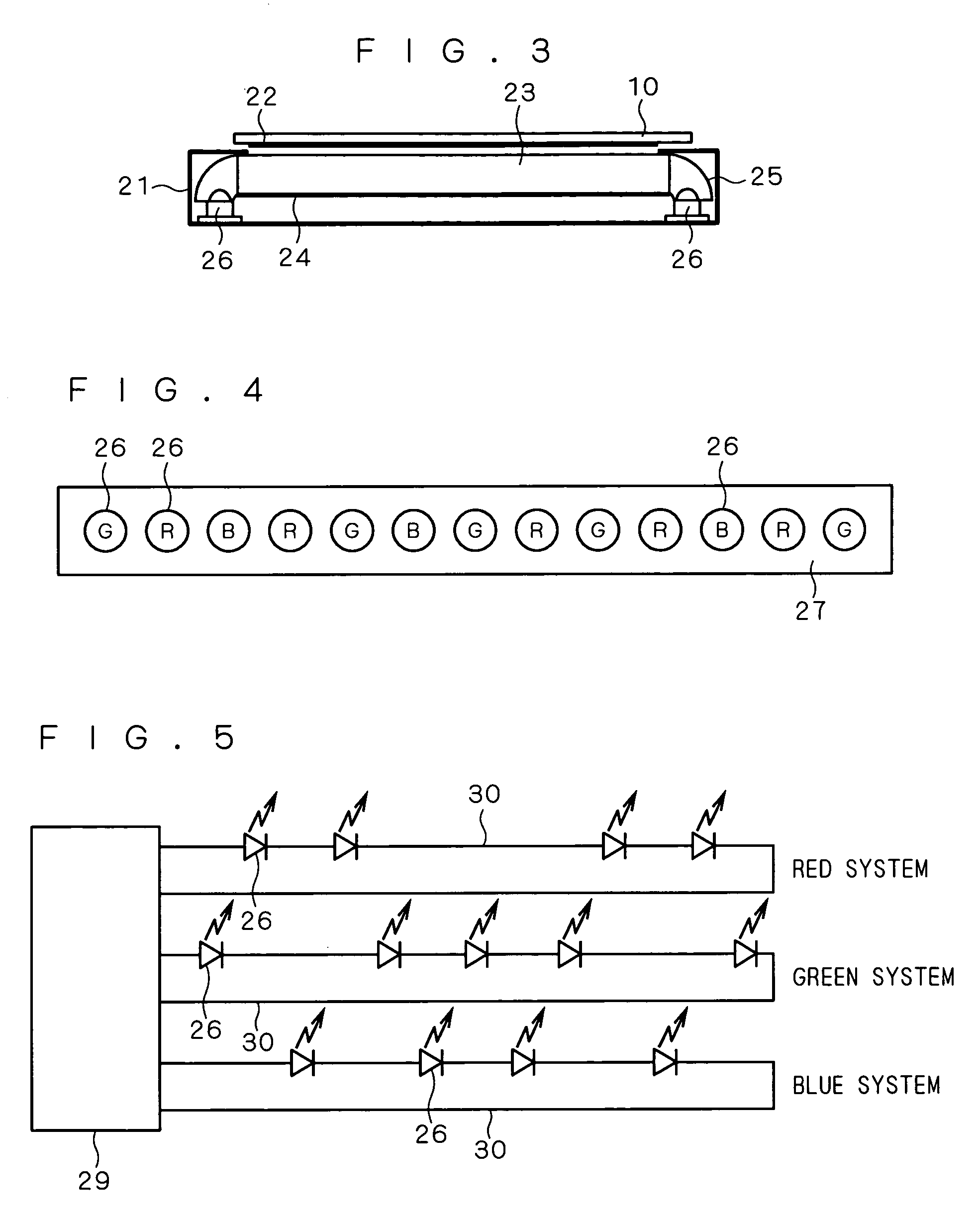
[0062]FIG. 9 illustrates the structure of the light source unit 28 in a planar light source device according to a second preferred embodiment of the present invention. FIG. 10 is a wiring diagram of the light source unit 28 in FIG. 9. In the light source unit 28 according to the second preferred embodiment, the R, G, and B LEDs 26 are mounted in a row on the rectangular circuit substrate 27, and LEDs 31 of wavelength longer than that of the R LEDs 26 are further mounted. In FIG. 9, the LEDs 31 are provided off the upper right of the third LED 26 from the left, and off the upper left of the third LED 26 from the right. The LEDs 31 are infrared (IR) LEDs having an infrared wavelength (at least 780 nm) as a dominant wavelength. The circles indicating the LEDs 31 in FIG. 9 are labeled with “IR”.

[0063]One IR LED 31 may be mounted on one light source unit 28, however at least two IR LEDs 31 should be mounted in order to detect averaging light without being affected by unevenness in color ...


PUM


Abstract

A planar light source device includes a light source section having a plurality of light emitting diodes as a light source, and a light guiding plate guiding light from the light source section to emit planar light. The light emitting diodes being turned off detect the quantities of light from the other light emitting diodes, and adjust the quantities of light emission of the other light emitting diodes based on the detected quantities of light.

Description

BACKGROUND OF THE INVENTION[0001]1. Field of the Invention[0002]The present invention relates to planar light source devices and display devices using the same, and particularly to planar light source devices using light emitting diodes and display devices using the same.[0003]2. Description of the Background Art[0004]As a planar light source device having a light emitting diode (LED) as a light source, a backlight of a liquid crystal display device used in a personal computer and the like has been conventionally well known. This planar light source device includes a light guiding plate for confining light, and a light source section. The light guiding plate is made of resin that is transparent and has a high refractive index, such as polycarbonate resin or acrylic resin. A light emission section is formed by mounting a plurality of LEDs on a substrate, and is arranged on opposite side surfaces of the light guiding plate.[0005]In order to obtain stabilized luminance with this device...

Claims


Application Information

Patent Timeline
Patent Type & Authority Patents(United States)
IPC IPC(8): F21V7/04F21S2/00F21V8/00F21Y101/02H05B37/02
CPCG02B6/0068G09G3/3413G09G3/342H05B33/0869H05B33/0803H05B33/0818H05B33/0857G09G2320/064G09G2360/145H05B45/22H05B47/16Y02B20/40
Inventor SAKAI, SEIJIYONEDA, TOSHIYUKI
Owner MITSUBISHI ELECTRIC CORP
Why Eureka
Try Eureka