Integral motor and air bearing cooling path

a cooling path and integrated technology, applied in bearing cooling, magnetic circuit rotating parts, magnetic circuit shapes/forms/construction, etc., can solve the problems of increasing the load on the thrust bearing, increasing the cost and and ungleich size of the journal bearing used to support the rotor assembly, so as to reduce the complexity of the assembly of the motor and reduce the cost

Active Publication Date: 2008-07-01
HAMILTON SUNDSTRAND CORP
View PDF17 Cites 85 Cited by
  • Summary
  • Abstract
  • Description
  • Claims
  • Application Information

AI Technical Summary

Benefits of technology

[0008]Accordingly, the present invention is a load design for the thrust bearings that minimizes cost and reduces complexity assembling the motor.

Problems solved by technology

The imbalanced loading on the rotor assembly increases the load on the thrust bearing, which is undesirable.
Typically, the journal bearings used to support the rotor assembly are of an unequal size to compensate for the imbalance of loads resulting from the different pressures.
The different bearings and seals add cost and complexity to the assembly of the motor.

Method used


Image

  • Integral motor and air bearing cooling path
  • Integral motor and air bearing cooling path
  • Integral motor and air bearing cooling path

Examples


Embodiment Construction

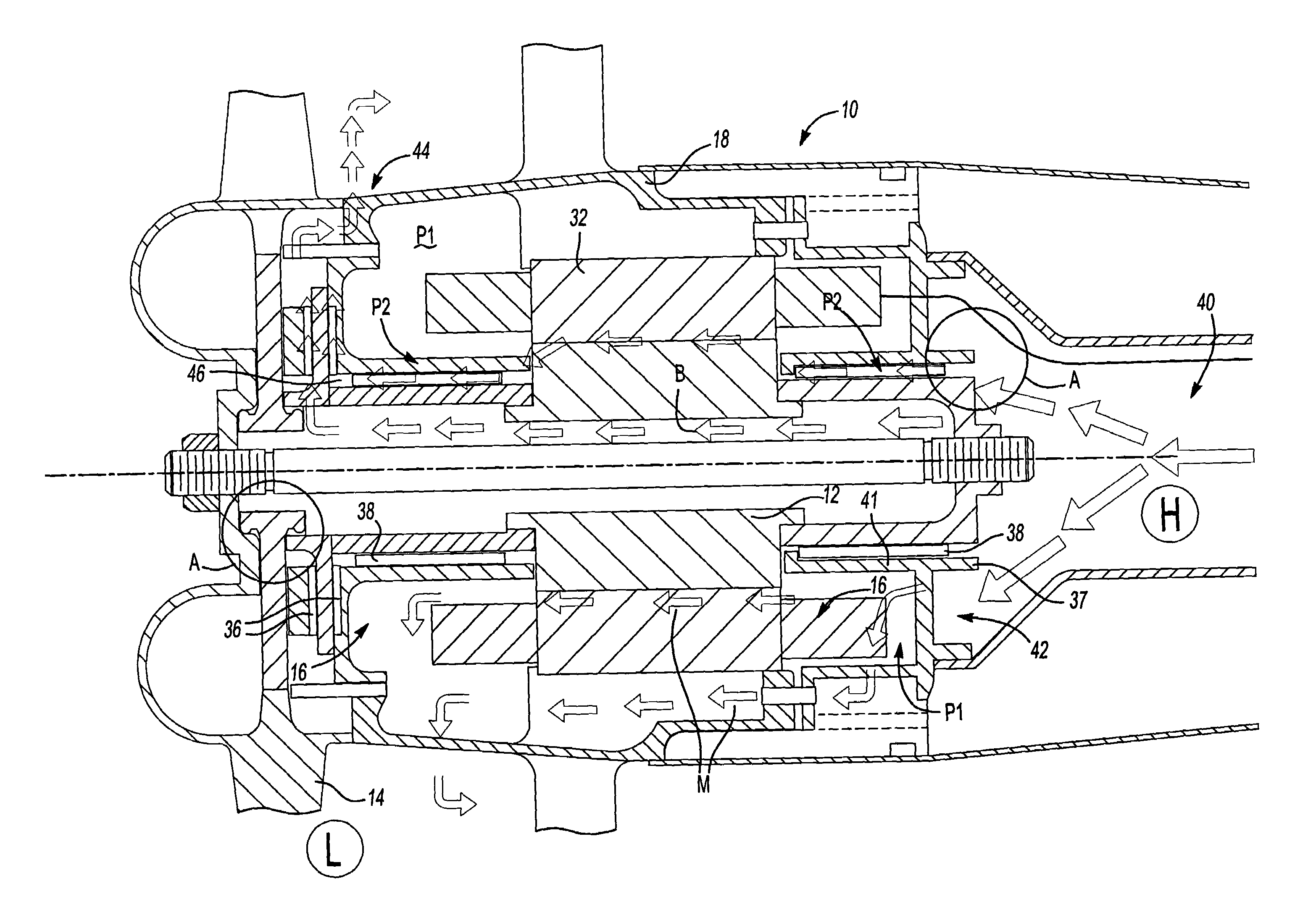
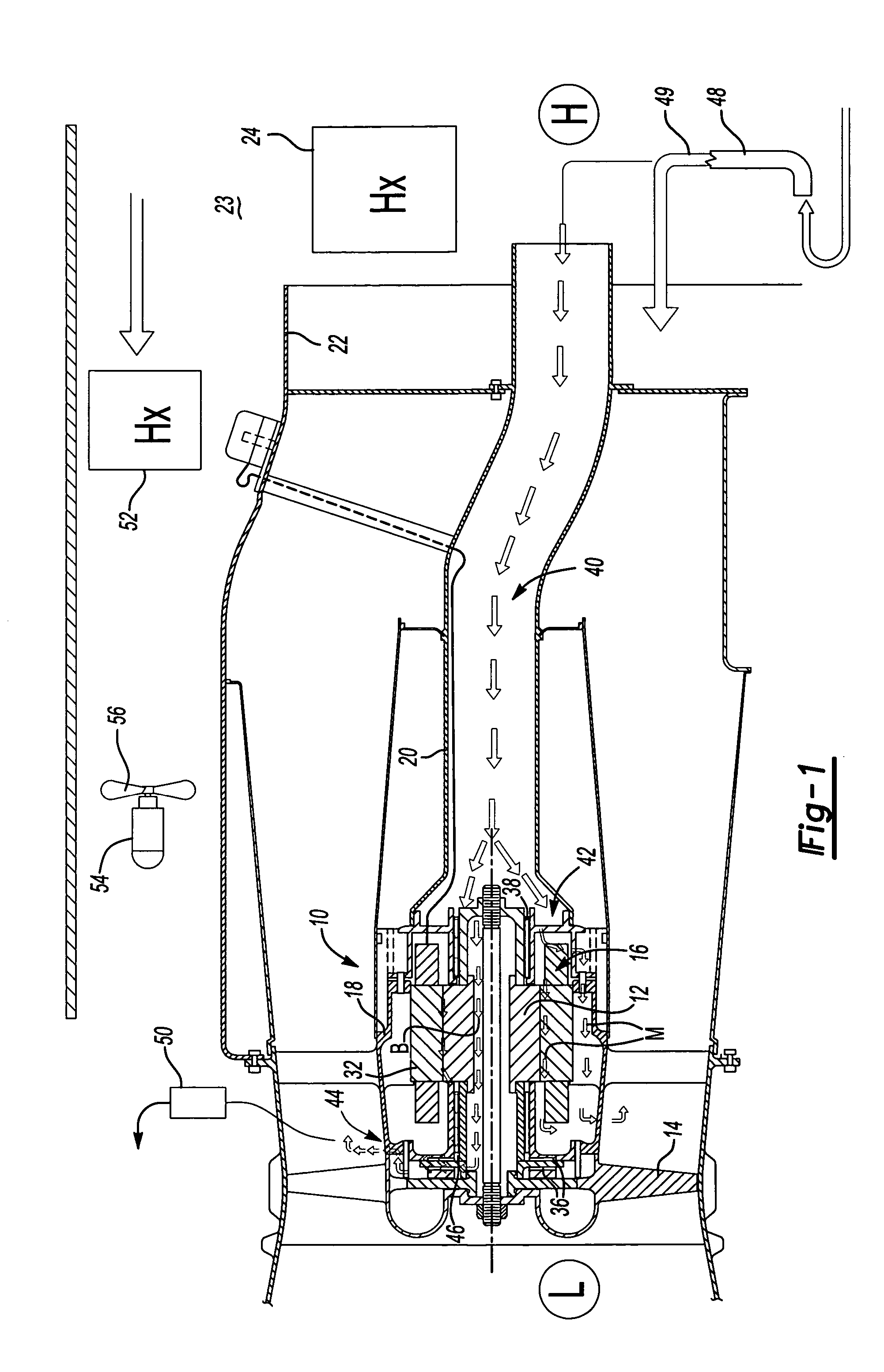
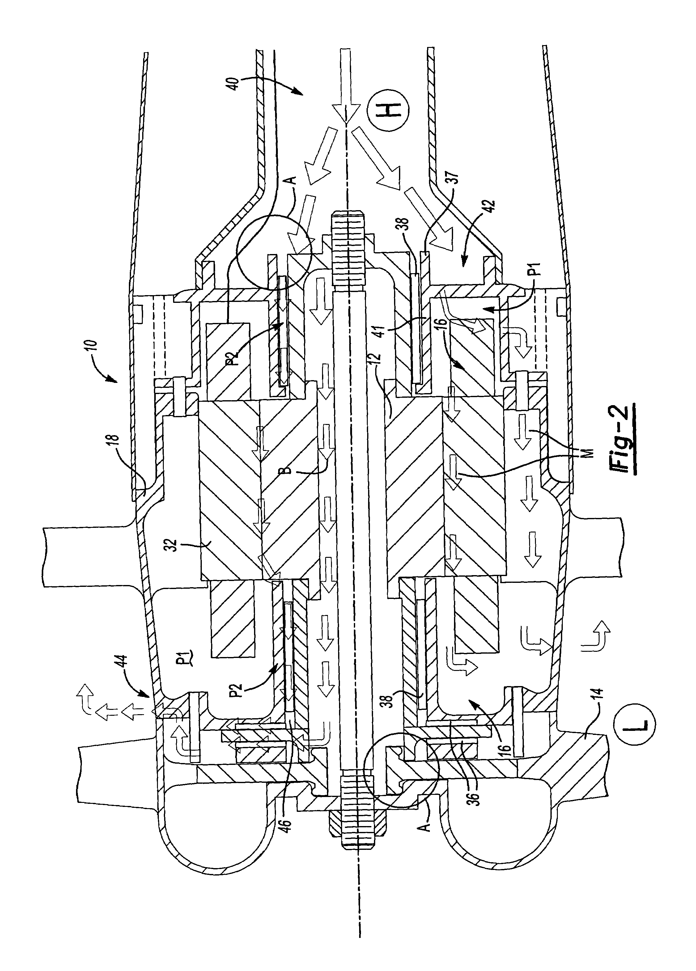
[0012]An air unit 10 is shown in FIGS. 1 and 2. The unit 10 includes a fan rotor 12 supporting rotor blades 14. An electric motor 16 rotatably drives the fan rotor 12.

[0013]The motor 16 is arranged in a motor housing 18, and an inlet housing 20 is secured to the motor housing 18. The inlet housing 20 provides an inlet 22 for supplying air to the rotor blades 14. In the example shown, the inlet 22 receives air from a ram air duct 23. The rotor blades 14 pull atmospheric air through a heat exchanger 24 (shown schematically) and discharge the air overboard.

[0014]The motor 16 includes a stator 32 arranged within the motor housing 18 that produces a magnetic field, which generates heat, causing the fan rotor 12 to rotate. The fan rotor 12 is supported by a thrust bearing 36 and journal bearings 38 arranged on either end of the fan rotor 12, in the example shown. A support 37 is secured to the motor housing 18 to support one of the journal bearings 38.

[0015]A passage 40 is in fluid commun...


PUM


Abstract

A motor is provided including a housing having single and integral motor and bearing cooling inlets. The motor is arranged within the housing and includes a stator and a rotor assembly supported on air bearings. The cooling inlet is in fluid communication with the motor stator and with the air bearings. The motor cooling inlet provides and the bearing cooling inlet provides a uniform pressure on the rotor assembly. The uniform pressures exerted on the rotor assembly produce bearing loads that generally cancel one another. The source of the cooling flow is uncompressed air at low pressure. This may be achieved by providing a vent in the housing that is common to both the motor cooling inlet and the bearing cooling inlet. As a result, journal bearings and seals of substantially the same size may be used.

Description

[0001]The present application claims priority to U.S. Provisional Application Ser. No. 60 / 611,921, filed Sep. 22, 2004.BACKGROUND OF THE INVENTION[0002]This invention relates to a motor cooling path and thrust bearing load design.[0003]Conventionally, electric motors have a rotor assembly driven by a stator. Motors subject to high heat may use air bearings, particularly, journal and thrust bearings. The air bearings and stator of an electric motor have been cooled using two airflow paths that are separate from one another. That is, the airflow paths have separate inlets and separate outlets. As a result of using separate flow paths, the bearings are subject to different loads based upon the different pressures in the flow paths that are exerted on the rotor assembly, bearings, and seals. The imbalanced loading on the rotor assembly increases the load on the thrust bearing, which is undesirable.[0004]It is desirable to balance the loads so that the net axial load on the thrust bearin...

Claims


Application Information

Patent Timeline
Patent Type & Authority Patents(United States)
IPC IPC(8): H02K9/00
CPCH02K1/20H02K1/32H02K5/161F04D25/082H02K7/14H02K9/06F16C37/00H02K7/083F16C37/002F04D19/00F04D25/0606F04D29/057F04D29/5806F04D29/584F04D29/0513
Inventor MCAULIFFE, CHRISTOPHERBEERS, CRAIGZYWIAK, THOMAS
Owner HAMILTON SUNDSTRAND CORP
Why Eureka
Try Eureka