
Rear-window roller blind without residual open gap

a technology of window blinds and roller blinds, which is applied in the direction of monocoque constructions, superstructure sub-units, building components, etc., can solve the problems of unavoidable gap in the known arrangement and especially vulnerable rear windows

Active Publication Date: 2008-07-08
BOS
View PDF9 Cites 21 Cited by
  • Summary
  • Abstract
  • Description
  • Claims
  • Application Information

AI Technical Summary

Benefits of technology

The present invention provides a window roller blind for motor vehicles, particularly a rear-window roller blind, which eliminates light gaps between the pull rod assembly and the window edge when the blind is in its extended position. The pull rod assembly is guided and carried over its entire path of travel between its rest position and its functional position. The pull rod assembly is adjustable in length to accommodate windows with varying widths. The guide elements ensure good guidance of the pull rod assembly. The drive device includes an electric motor for remote activation or manual activation, and linear activation elements for transferring the activation force from the motor to the roller blind. The contoured plate of the pull rod assembly closes the gap between the pull rod assembly and the window edge when the pull rod assembly is in its functional position. The pull rod assembly is formed with a recess or depression that matches the shape of the contoured plate so that the contoured plate largely disappears and flush with the rear shelf when the blind is retracted.

Problems solved by technology

In terms of direct sun irradiation, in the summer when the sun rises high in the sky, the rear window is especially vulnerable because it lies relatively flat.
The gap is unavoidable in the known arrangement due to the straight profile in the pull rod assembly.

Method used


Image

  • Rear-window roller blind without residual open gap
  • Rear-window roller blind without residual open gap
  • Rear-window roller blind without residual open gap

Examples


Embodiment Construction

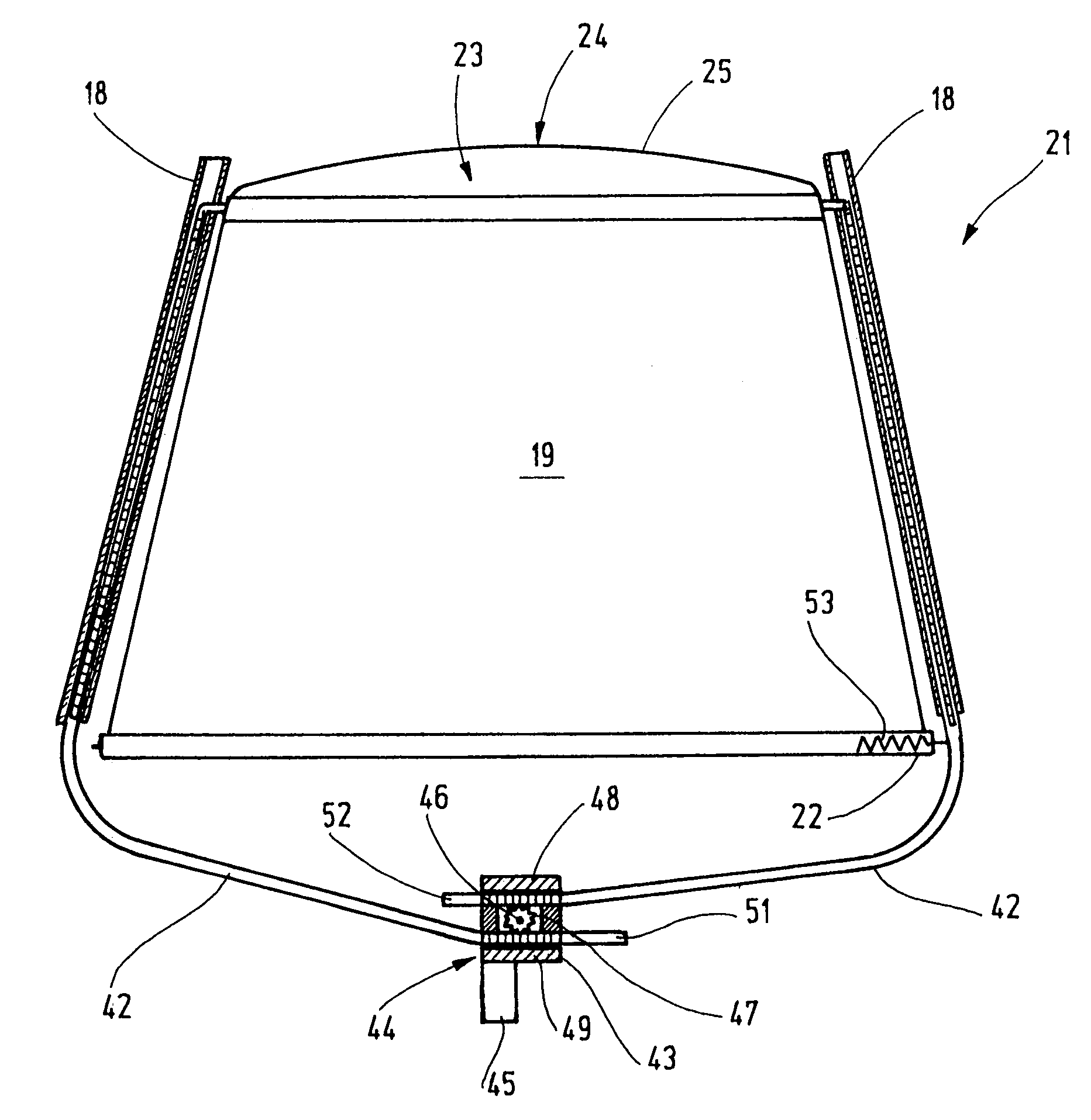
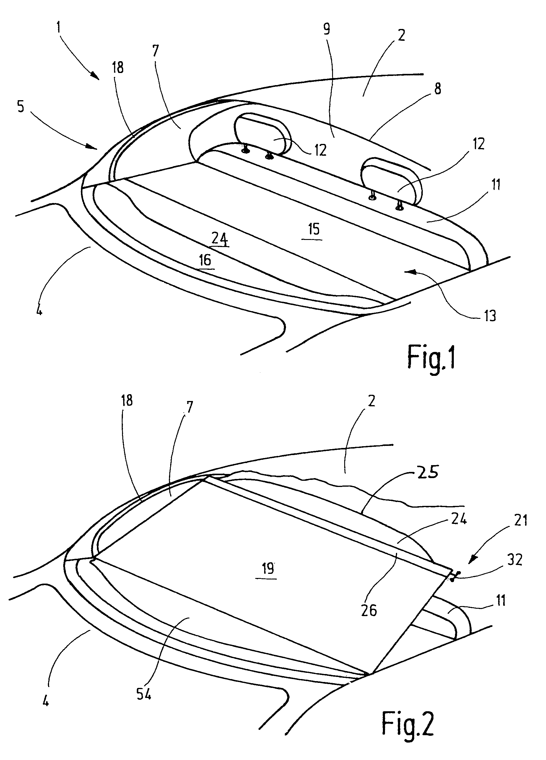
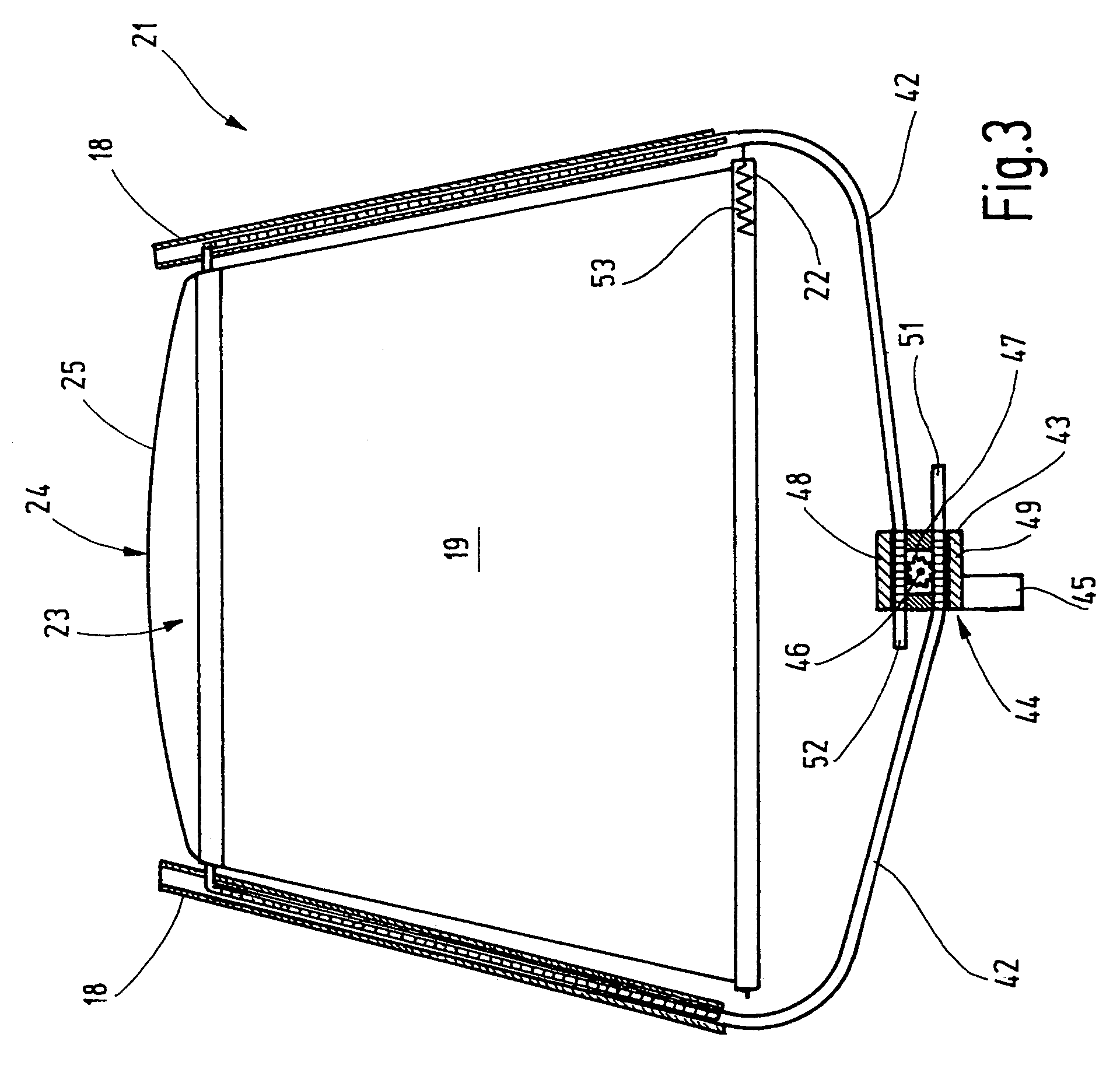
[0023]Referring now more particular to FIG. 1 of the drawings, there is shown a rear section 1 of a motor vehicle sedan having a rear window roller blind in accordance with the invention. The illustrative motor vehicle has a roof 2, a trunk lid 4, and C-shaped columns 5 having a lining 7 disposed between the trunk lid 4 of the motor vehicle and the roof 2. Between the C-shaped columns 5, a rear edge 8 of the roof 2 and, a top side of the trunk 4, a rear window cut-out 9 is defined in which a rear window 10 (FIG. 5) is located. Between the bottom edge of the rear window cut-out 9 and the rear side of a rear seat bench 11 with head supports 12, a rear shelf 13 extends approximately horizontally. A slot 14 (FIG. 5), which divides the rear shelf 13 into a front section 15 and a rear section 16, runs transversely through the rear shelf 13. Laterally next to the slot 14, two mirror-shaped guide rails 18 are integrated into the inner lining parts 7 of the C-columns 5. The mirror shaped gui...


PUM


Abstract

A rear window roller blind for motor vehicles which has a pull rod assembly with a contoured plate. The contoured plate is used to close the segmented residual gap between the straight pull rod assembly and the curved top edge of the rear window. In order for the contoured plate to lie flush with a rear shelf below the rear window when the roller blind is in a retracted position, it is pivotable about a longitudinal axis of the pull rod assembly during movement of the pull rod between its retracted and extended positions. Such rotational movement is controlled by the contour of guide rails within which the pull rod is guided during such pull out movement.

Description

FIELD OF THE INVENTION[0001]The present invention relates generally to window roller blinds for motor vehicles, and more particularly, to motor vehicle window roller blinds that are automatically extendable and retractable.BACKGROUND OF THE INVENTION[0002]Window roller blinds in motor vehicles are used for the purpose of reducing interior heating in order to minimize air-conditioning system requirements. In terms of direct sun irradiation, in the summer when the sun rises high in the sky, the rear window is especially vulnerable because it lies relatively flat. Depending on the driving direction, sunlight nearly always comes through the rear window and the exposed parts of the vehicle beneath the rear window are heated significantly. Therefore, rear-window roller blinds have become relatively widely used in vehicles.[0003]In a known rear-window roller blind shown in DE 102 48 591 A1, a rotatably supported wind-up shaft is located underneath a rear shelf below the window. A roller bl...

Claims


Application Information

Patent Timeline
Patent Type & Authority Patents(United States)
IPC IPC(8): B60J3/02
CPCB60J1/2027B60J1/208B60J1/2052B60J1/2044B60J1/20B60J3/00B60J3/02
Inventor THUMM, ANDREASKEBEDE, FEKADU
Owner BOS
Learn More