Scatter correction for CT method and apparatus

a ct method and ct technology, applied in the field of non-invasive imaging, can solve the problems of blurring or generally poor image quality, artifacts in the resulting image, and inconvenient composition or structural information,

Active Publication Date: 2008-07-08
MORPHO DETECTION INC
View PDF1 Cites 27 Cited by
  • Summary
  • Abstract
  • Description
  • Claims
  • Application Information

AI Technical Summary

Benefits of technology

[0006]A method for correcting scatter in an image is provided. The method includes the act of emitting radiation from one or more sources of radiation towards a detector array and measuring radiation on areas of the detector array that are not

Problems solved by technology

However, various physical factors associated with the X-ray imaging process may lead to artifacts in the resulting images or to blurring or generally poor image quality.
As a result, a scattered X-ray photon may impact the detector at a location or from a direction that conveys no useful composition or structural information about the patient or object undergoing imaging.
As a result, the scattered X-ray photons may lead to blur within the resulting radiographic image or otherwise reduce the image quality, such as CT number nonuniformity or a reduction in the contrast-to-noise ratio in a reconstructed image.
In order to reduce sc

Method used


Image

  • Scatter correction for CT method and apparatus
  • Scatter correction for CT method and apparatus
  • Scatter correction for CT method and apparatus

Examples


Embodiment Construction

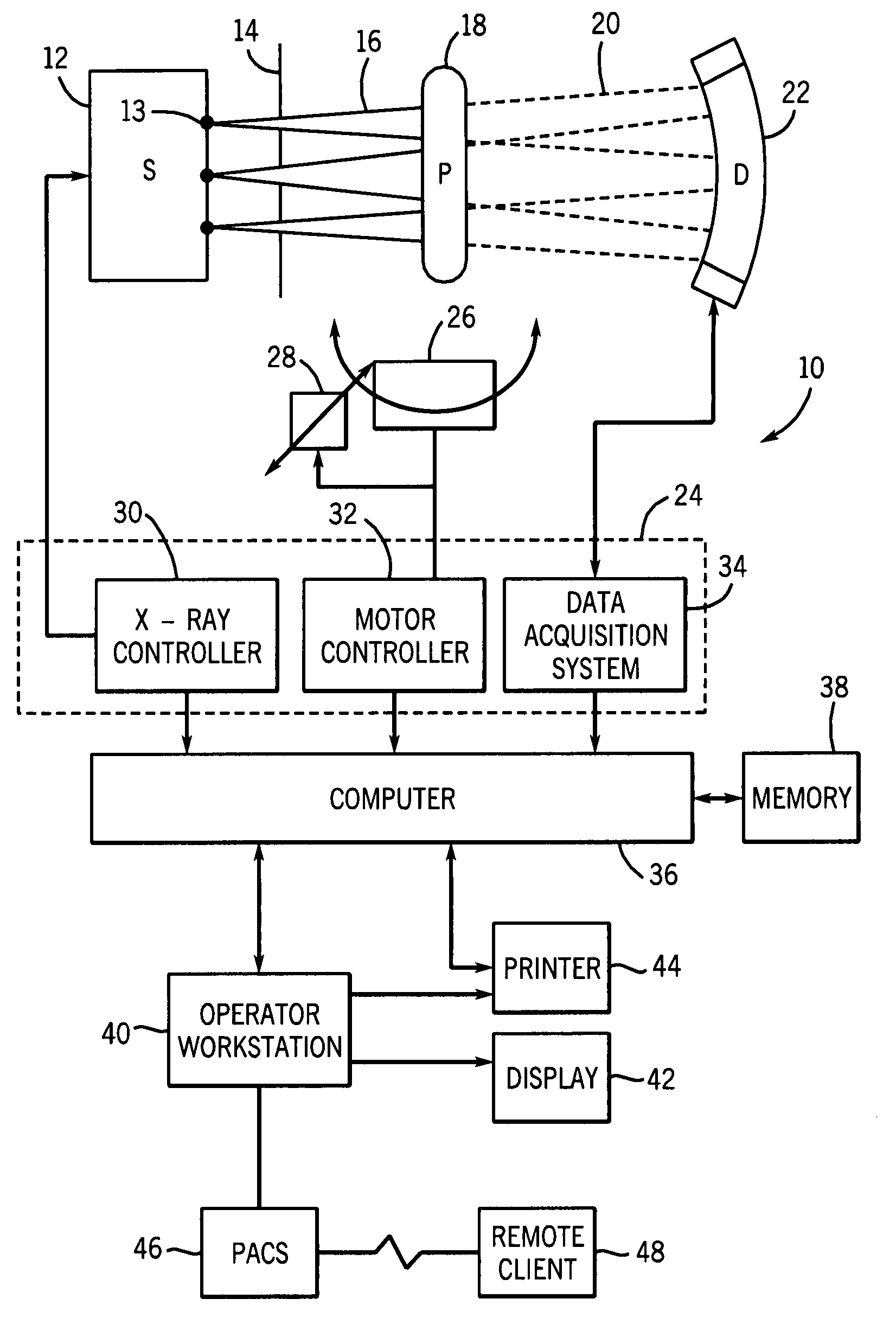
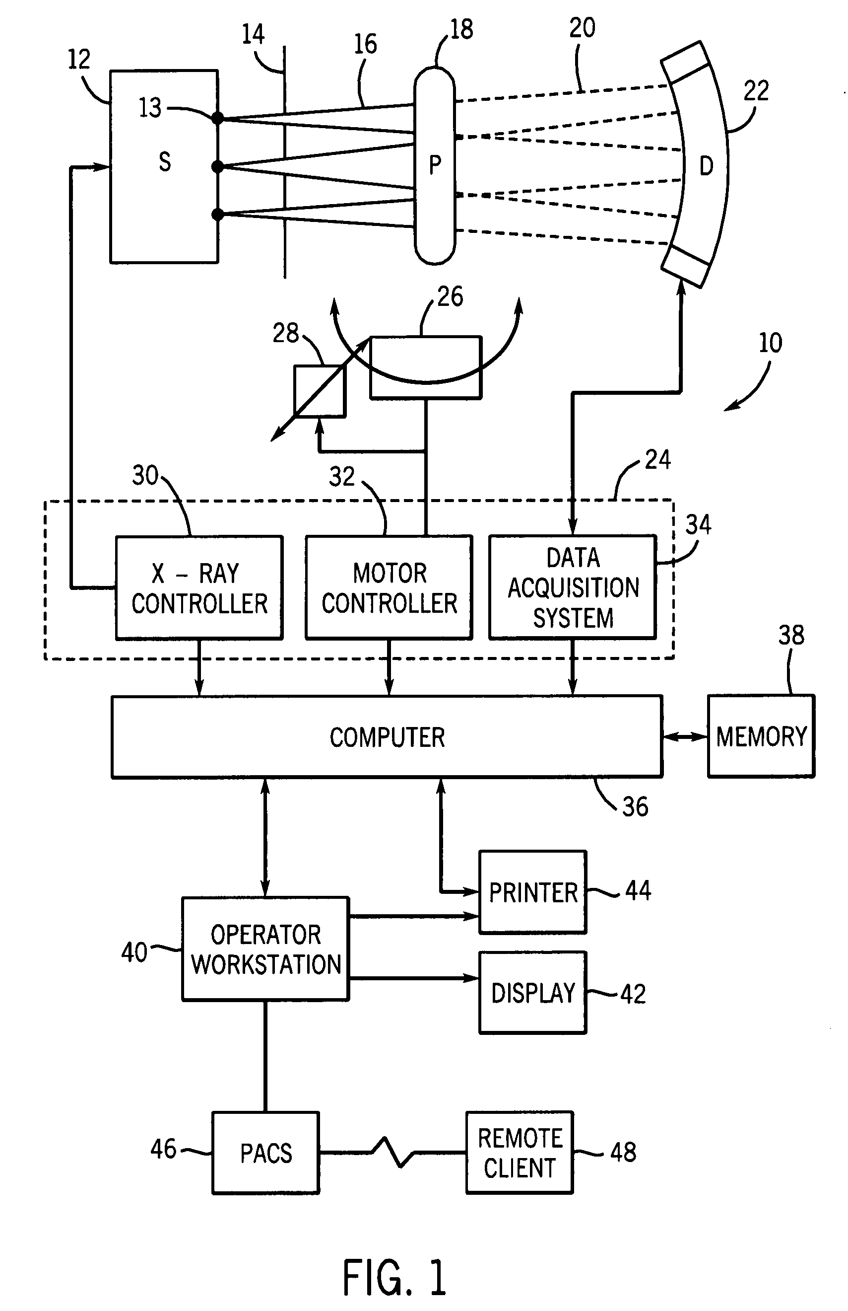
[0014]FIG. 1 illustrates diagrammatically an imaging system 10 for acquiring and processing image data. In the illustrated embodiment, system 10 is a computed tomography (CT) system designed to acquire X-ray projection data, to reconstruct the projection data into an image, and to process the image data for display and analysis in accordance with the present technique. Though the imaging system 10 is discussed in the context of medical imaging, the techniques and configurations discussed herein are applicable in other non-invasive CT imaging contexts, such as baggage or package screening. In the embodiment illustrated in FIG. 1, CT imaging system 10 includes a source 12 of X-ray radiation. As discussed in detail herein, the source 12 of X-ray radiation may be any source configured to emit X-rays from one or more z-locations or emission points 13. For example, the X-ray source 12 may consist of multiple X-ray tubes arranged at different locations along the z-axis. Similarly, the X-ra...


PUM


Abstract

A method, system, and machine readable media are provided for correcting scatter in an image. The method comprises sequentially emitting radiation from a subset of radiation sources toward a detector array and measuring radiation on areas of the detector array not exposed to the emitted primary radiation at the time of measurement. Scatter is estimated from the measured radiation. Furthermore, the scatter estimates are subtracted from the measured data and images with improved image quality are reconstructed.

Description

BACKGROUND[0001]The present invention relates generally to the field of non-invasive imaging and more specifically to the field of computed tomography. In particular, the present invention relates to improving image quality by estimating and reducing scatter in an X-ray imaging system.[0002]CT scanners operate by emitting fan-shaped or cone-shaped X-ray beams from an X-ray source towards a detector. The X-ray source emits X-rays at numerous angular positions relative to an object being imaged, such as a patient, which attenuates the X-ray beams as they traverse the object. The attenuated X-ray beams are detected by a set of detector elements, which produce signals representing the attenuation of the incident X-ray beams. The signals are processed to produce data corresponding to the line integrals of the attenuation coefficients of the object along X-ray paths connecting the source and detector elements. These signals are typically called “projection data” or just “projections”. By ...

Claims


Application Information

Patent Timeline
IPC IPC(8): G01D18/00
CPCA61B6/5282G01T1/2985G01T1/1647A61B6/4291
Inventor EDIC, PETER MICHAELBASU, SAMIT KUMAR
Owner MORPHO DETECTION INC
Why Eureka
Try Eureka