Air filter having fluted filter media

a filter media and air filter technology, applied in the direction of filtration separation, combustion-air/fuel-air treatment, separation process, etc., can solve problems such as substantial damag

Active Publication Date: 2008-07-08
DONALDSON CO INC
View PDF151 Cites 211 Cited by
  • Summary
  • Abstract
  • Description
  • Claims
  • Application Information

AI Technical Summary

Problems solved by technology

The particulate material, should it reach the internal workings of the various mechanisms involved, can cause substantial damage thereto.

Method used


Image

  • Air filter having fluted filter media
  • Air filter having fluted filter media
  • Air filter having fluted filter media

Examples


Embodiment Construction

A. Example System and Overview of the Air Cleaner

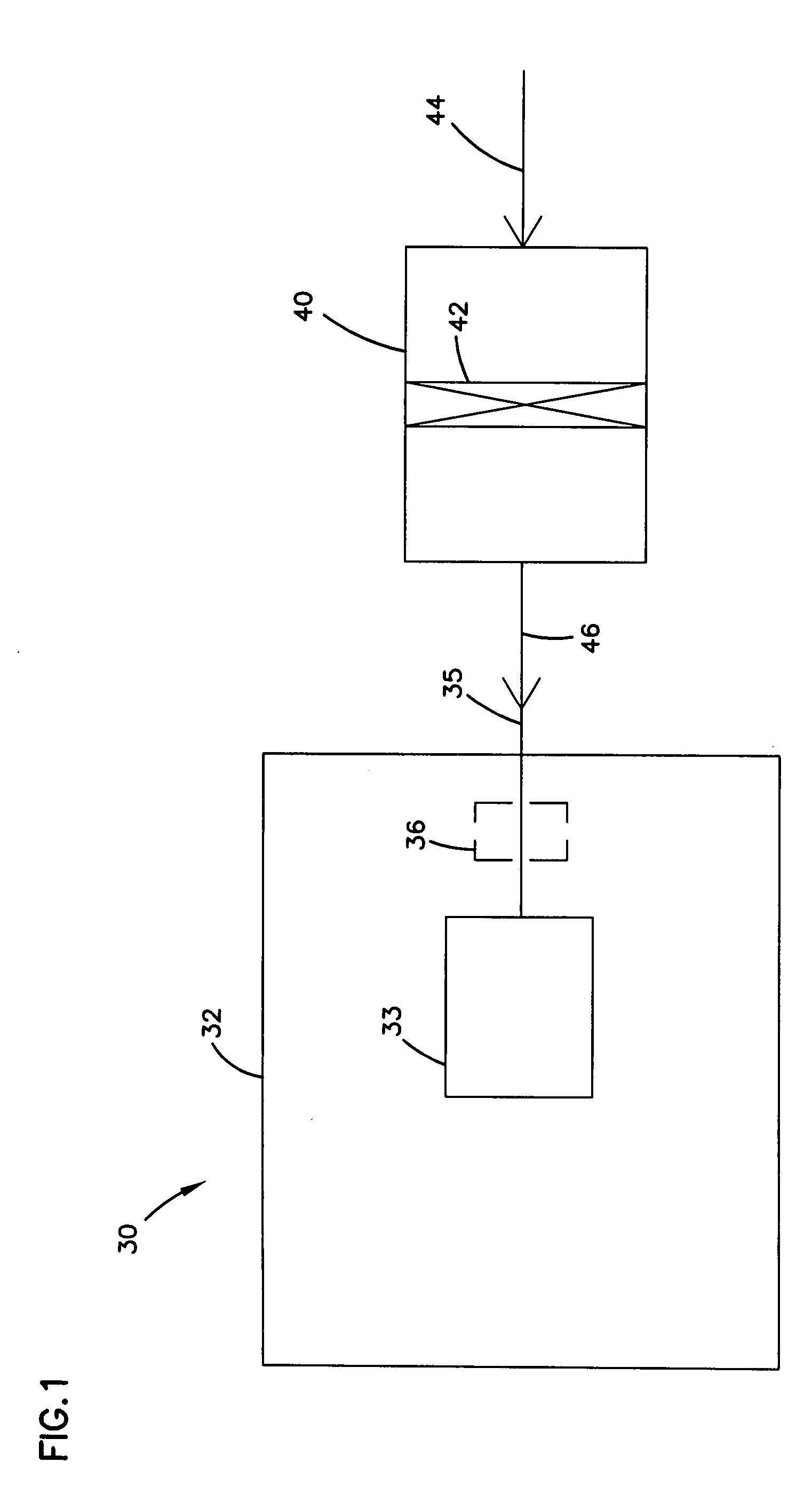
[0041]Filter constructions and arrangements described herein are usable in a variety of systems. One particular type of system is depicted schematically in FIG. 1 generally at 30. In FIG. 1, equipment 32, such as a vehicle, having an engine 33 with some defined rated air flow demand, for example at least 50 cfm and up to 1800 cfm, is shown schematically. The equipment 32 may comprise a bus, an over-the-highway truck, an off-road vehicle, a tractor, a light-duty or medium duty truck, or a marine application such as a powerboat. The engine 33 powers the equipment 32, through use of an air and fuel mixture. In FIG. 1, air flow is shown drawn into the engine 33 at an intake region 35. An optional turbo 36 is shown in phantom, as optionally boosting the air intake into the engine 33. An air cleaner 40 having a filter construction 42 is upstream of the engine 33 and the turbo 36. In general, in operation, air is drawn in at arrow 44 into th...


PUM

PropertyMeasurementUnit
lengthaaaaaaaaaa
lengthaaaaaaaaaa
internal volumeaaaaaaaaaa

Abstract

An air cleaner (40) includes a housing (48) and an access cover. The internal volume of the housing (48) can be reached through an opening (70) in a side wall of the housing. A filter element (50) having fluted filter media is removable and replaceable from the air cleaner (40). The housing is constructed and arranged to cam the element (50) into sealing engagement with the housing (48). The access cover includes structure to help support and ensure proper seating of the filter element within the housing. A method of installing the filter element in the air cleaner includes sliding a portion of the filter element against a slide surface in the housing. A method of servicing an air cleaner includes tilting the filter element against a tilt surface in the housing to release a seal between the filter element and the housing. The filter element can have a handle to assist in servicing of the air cleaner. The housing can have a window to allow visual inspection of the internal component of the housing and to determine visually whether a filter element is installed therein.

Description

CROSS REFERENCE TO RELATED APPLICATION[0001]This patent application is a National Stage application of PCT Patent Application Serial No. PCT / US03 / 14350, filed May 8, 2003 and claims priority to U.S. Ser. No. 60 / 379,824 filed on May 9, 2002.TECHNICAL FIELD[0002]This disclosure concerns filter constructions for engines and methods of filtering and filter preparation. In particular, the disclosure describes Z-filter arrangements and side entry housings.BACKGROUND[0003]Gas streams often carry particulate material therein. In many instances, it is desirable to remove some or all of the particulate material from a gas flow stream. For example, air intake streams to engines for motorized vehicles or power generation equipment, gas streams directed to gas turbines, and air streams to various combustion furnaces, often include particulate material therein. The particulate material, should it reach the internal workings of the various mechanisms involved, can cause substantial damage thereto....

Claims


Application Information

Patent Timeline
Patent Type & Authority Patents(United States)
IPC IPC(8): B01D46/00B01D46/24F02M35/024B01D46/42B01D46/52
CPCB01D46/0004B01D46/0005B01D46/2411B01D46/42B01D46/525B01D46/527B01D46/4227Y10T29/49826B01D2265/025B01D2271/027B01D46/52B01D46/0002B01D46/0006
Inventor NEPSUND, LARRY R.KUEMPEL, BRADLEY A.ENGEL, DONALD F.BOEHRS, BRUCE ALLENANDERSON, SHELDONBUCHOLTZ, RICHARD L.LUNDGREN, THOMAS JOHN
Owner DONALDSON CO INC
Why Eureka
Try Eureka