Connector

a technology of connecting rods and connectors, applied in the direction of connection contact material, connection device connection, respirator, etc., can solve the problems of patient problems, condensation of water vapour,

Active Publication Date: 2008-07-08
FISHER & PAYKEL HEALTHCARE LTD
View PDF13 Cites 37 Cited by
  • Summary
  • Abstract
  • Description
  • Claims
  • Application Information

AI Technical Summary

Benefits of technology

[0006]It is an object of the present invention to provide a tubing connector between heated breathing conduits and / or patient interfaces that goes some way towards overcoming the abovementioned disadvantages.
[0010]wherein coupling of said male and said female portions causes said electrical contact means to engage with said electrical receiving means, said coupling simultaneously causing a gaseous and electrical connection between said first conduit and one second conduit, and said coupling being able to be swivelled or twisted without disrupting said gaseous and electrical connection.

Problems solved by technology

In such a case where the gases have been humidified, and therefore laden with water, it is likely that during transport through a conduit to the patient, condensation of that water vapour will occur.
It has been found that condensation may form in the short flexible connecting tube causing problems to the patient.

Method used


Image

  • Connector
  • Connector
  • Connector

Examples


Embodiment Construction

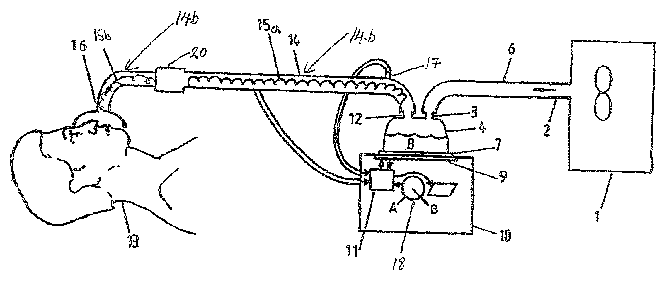
[0025]The present invention provides improvements in the field of CPAP therapy. In particular to a connector that creates both an electrical and a gaseous connection between two conduits. This connection has the advantage of being able to be twisted and swivelled without loss of electrical or gaseous connection between the two conduits. It will be appreciated that the connector as described in the preferred embodiment of the present invention can be used in respiratory care generally or with a ventilator, but will now be described below with reference to use in a humidified CPAP system. It will also be appreciated that the connector is equally applicable to all forms of patient interface.

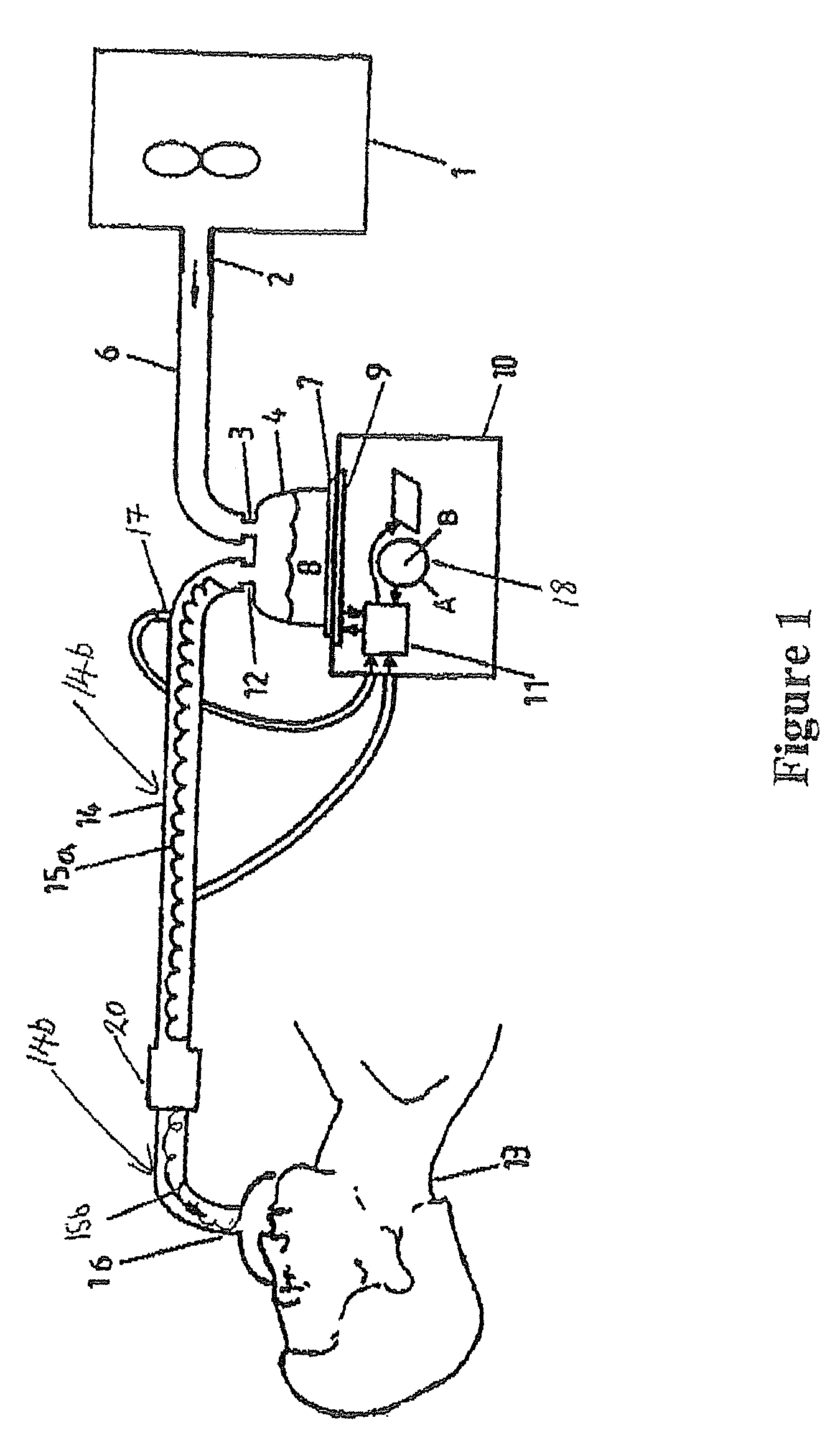
[0026]With reference to the accompanying drawings and in particular to FIG. 1, an example of humidification apparatus and respiratory humidification system incorporating preferred embodiments of the connector of the present invention is illustrated. In the description below, reference has been made ...


PUM


Abstract

A connector (20) to a couple breathing conduit to a patient interface or another conduit. The connector allows for an electrical connection (22a, 22b) in a first conduit (14a) to be connected to another electrical connection (21a, 21b) in a patient interface or second conduit (14b). The connector is capable of swivelling without disrupting the gas flow through the conduits of the electrical connection.

Description

BACKGROUND TO THE INVENTION[0001]1. Field of the Invention[0002]The present invention relates particularly, though not solely, to the delivery of humidified pressurised oxygen and / or air to a patient. In particular, the present invention relates to connections used to couple heated breathing conduits together.[0003]2. Summary of the Prior Art[0004]In order to supply gases to a patient or a person needing such gases, it may sometimes be necessary to first humidify those gases, for example using a respiratory humidifier / ventilator system. In such a case where the gases have been humidified, and therefore laden with water, it is likely that during transport through a conduit to the patient, condensation of that water vapour will occur. In order to overcome this disadvantage it is known to associate a heater wire with respiratory humidifier breathing conduits to avoid condensation. Examples of such a heated breathing conduit are disclosed in U.S. Pat. No. 5,537,996 (McPhee) and U.S. Pat...

Claims


Application Information

Patent Timeline
Patent Type & Authority Patents(United States)
IPC IPC(8): H01H9/02A61M16/08A61M16/10H01R13/00H01R35/04
CPCA61M16/08H01R13/005A61M16/1095A61M16/109H01R24/58H01R2107/00H01R2201/12H01R35/04
Inventor LAURENT, KRISTOPHER POH MINGMCAULEY, ALASTAIR EDWINNIGHTINGALE, CHRISTOPHER EARLMAKINSON, IAN DOUGLASMILIVOJEVIC, IVANWILSON, GRANT WARREN
Owner FISHER & PAYKEL HEALTHCARE LTD
Why Eureka
Try Eureka