Voltage measuring device

a voltage measurement and voltage technology, applied in the direction of resistance/reactance/impedence, moving-iron instruments, instruments, etc., can solve the problems of low interference structure, inability to use devices in many applications for accurate power factor and quality measurement, and inability to meet the requirements of high-voltage overhead power lines

Active Publication Date: 2008-07-08
SORENSEN THOMAS +1
View PDF4 Cites 20 Cited by
  • Summary
  • Abstract
  • Description
  • Claims
  • Application Information

AI Technical Summary

Problems solved by technology

However, it is apparent that the device shown in FIG. 1 can only be used in applications where the wire 12 can be threaded through the device or if the device has more than one moveable part that can be clipped or attached together.
Because of these restrictions, this low interference structure is virtually unused on high voltage overhead power lines.
The result is that the device is not usable in many applications for accurate power factor and quality measurements, particularly if an interfering phase is situated in the direction of the gap 20 in the device.

Method used


Image

  • Voltage measuring device
  • Voltage measuring device
  • Voltage measuring device

Examples


Embodiment Construction

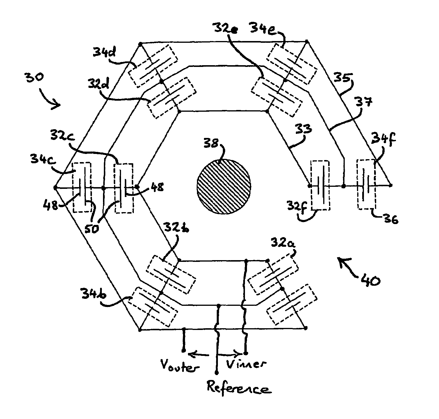
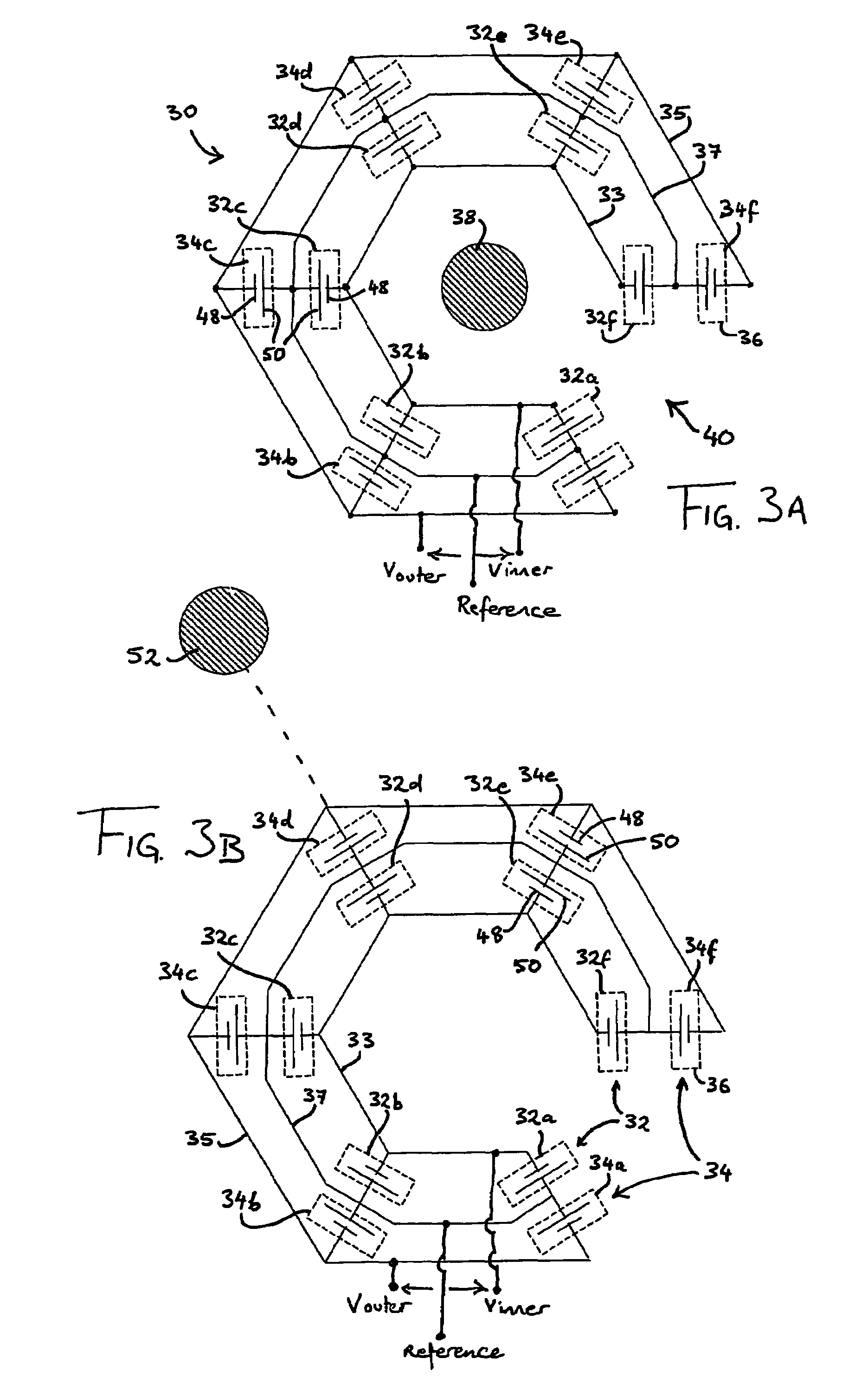
[0028]Referring to FIG. 3A, the voltage measuring device 30 comprises an electrically insulating motherboard (not shown in FIG. 3A but to be described with reference to FIGS. 5 to 7) upon which are mounted a plurality of capacitive voltage sensors 36. These sensors 36 comprise an inner set of sensors 32a-f and an outer set of sensors 34a-f. The inner and outer sets of sensors 32a-f and 34a-f are mounted in a substantially common plane and are substantially identical in construction. The inner set of sensors 32a-f are disposed at substantially equal intervals along a first notional circle 32 while the outer set of sensors 34a-f are disposed at substantially equal intervals along a second notional circle 34 concentric with the first circle 32. The sensors 36 are radially aligned in pairs relative to the common centre of the circles 32 and 34, i.e. 32a / 34a, 32b / 34b, etc.

[0029]Each sensor 36 is in the form of a parallel plate capacitor and has a signal electrode 48 and at least one refe...


PUM


Abstract

A device for measuring alternating voltage in a conductor under test using a first set of capacitive voltage sensors 32a-f mounted on an electrically insulating support member. The sensors are disposed on the support member at spaced intervals along a first notional circle and are connected in parallel between an inner signal conductor 33 and a zero voltage reference conductor 37. A second set of capacitive voltage sensors 34a-f are mounted on the support member at spaced intervals along a second notional circle and are connected in parallel between an outer signal conductor 35 and the reference conductor 37. The support member is configured to allow a conductor under test 38 to be introduced into the interior of the device so that the sensors surround the axis of the conductor. Each sensor has a signal electrode 48 connected to the signal conductor and a reference electrode 50 connected to the reference conductor and is orientated with the signal electrode facing the conductor under test. The voltage in the conductor under test is derived as a function of the voltage across the signal conductor and the reference conductor.

Description

FIELD OF THE INVENTION[0001]This invention relates to a device for measuring alternating voltage in a conductor under test, for example, an overhead AC power line.BACKGROUND OF THE INVENTION[0002]The measurement of power factor and power quality is an important aspect in the monitoring of electrical utilities. In order to calculate the power factor and quality of a particular AC power line, the alternating voltage and current of the line must be measured. For overhead power lines, removable contactless voltage measuring devices provide the best balance of ease of use and flexibility.[0003]FIG. 1 illustrates a non-contact voltage measuring device 10 as disclosed in JP2002131341. The figure shows a longitudinal section of an insulated conducting wire 12, to which an alternating voltage is applied with respect to ground. This is the voltage waveform to be observed by the device 10. The device 10 consists of two conducting pipes—an inner conductor 14 and an outer conductor 16—that surro...

Claims


Application Information

Patent Timeline
Patent Type & Authority Patents(United States)
IPC IPC(8): G01R19/00G01R27/26G01R31/02G01R5/14G01R15/16
CPCG01R15/16
Inventor SORENSEN, THOMAS
Owner SORENSEN THOMAS
Why Eureka
Try Eureka