
Mirrored decorative video display concealment and cooling apparatus and method

a video display and decorative technology, applied in the direction of electrical equipment casings/cabinets/drawers, television systems, instruments, etc., can solve the problems of large blank screen that interferes with the intended decor, the appearance of blank screen is not aesthetically pleasing, and the undesirable aspect of flat panel televisions and displays increases in proportion, so as to reduce speed, the effect of air cooling of the video display

Inactive Publication Date: 2008-07-08
GRAHAM JONATHAN W
View PDF5 Cites 32 Cited by
  • Summary
  • Abstract
  • Description
  • Claims
  • Application Information

AI Technical Summary

Benefits of technology

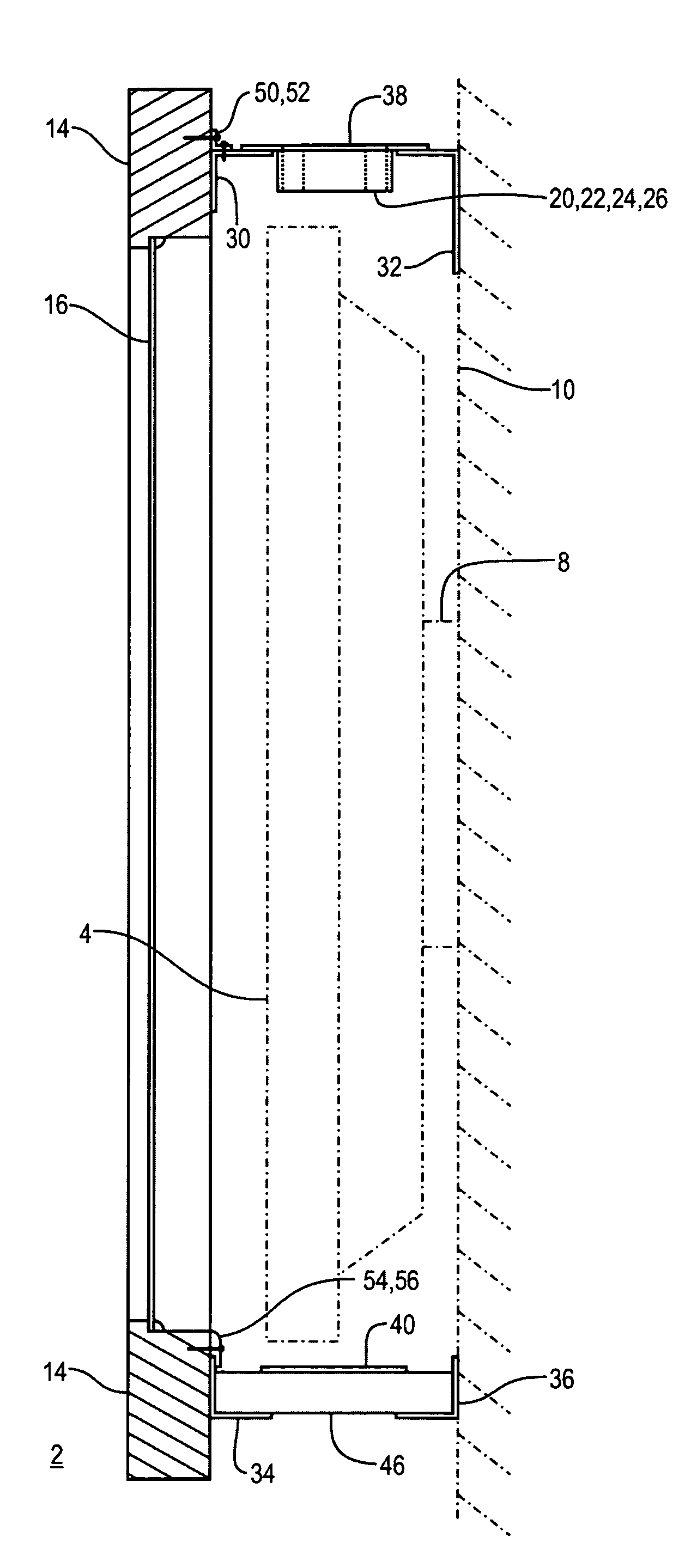
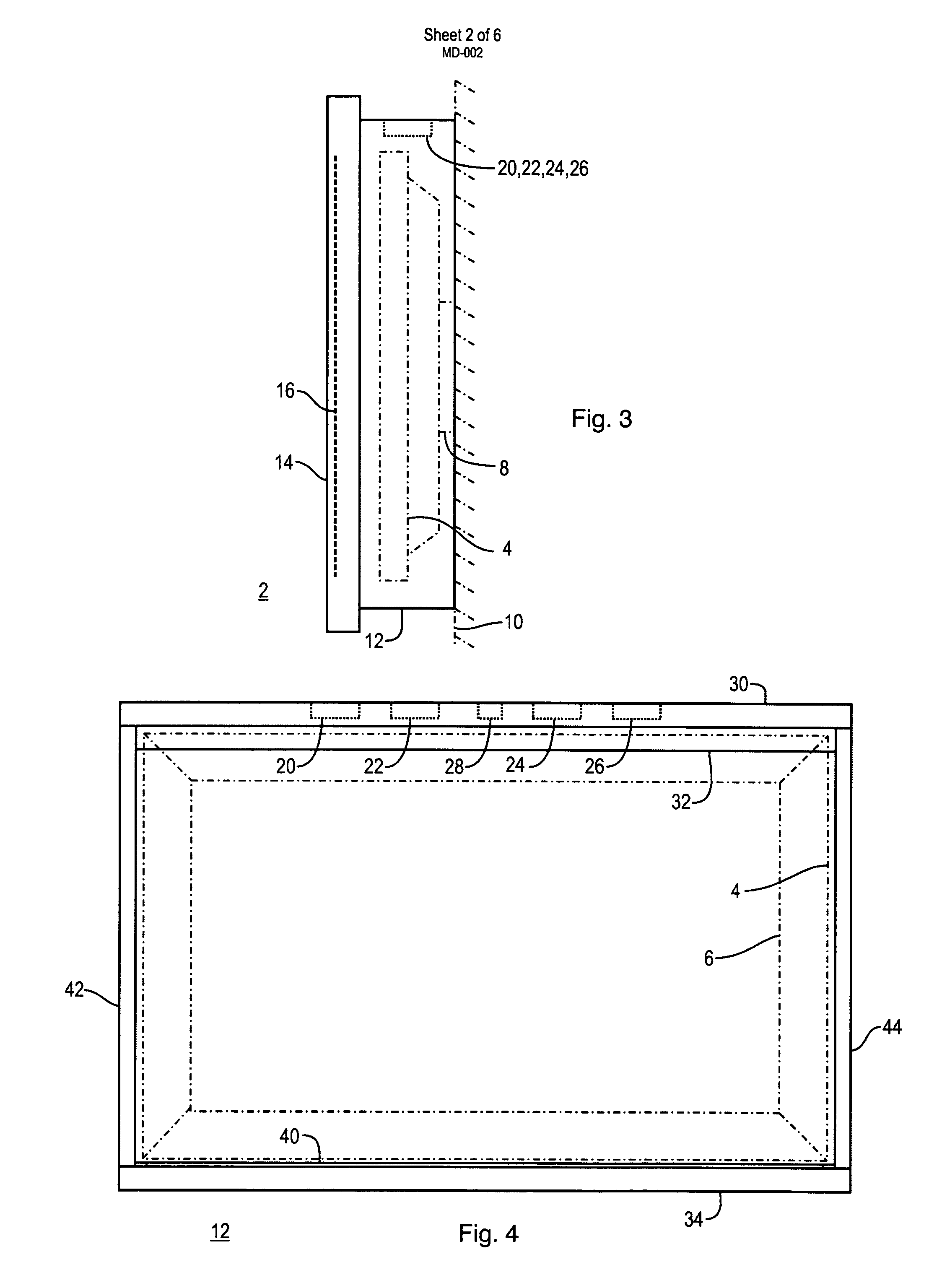
[0009]In another specific embodiment of the invention, the fan is attached to a top surface of the perimeter structure, and the fan is aligned to exhausting air from within the perimeter structure. The light baffle may be aligned with a bottom surface of the perimeter structure. In another embodiment, a fan control circuit is disposed within the perimeter structure, and is coupled to energize the fan and drives the fan at a reduced speed, thereby enabling quiet operation. In another specific embodiment, plural fans are coupled to the fan control circuit. A fan control circuit light baffle may be provided to block the visual appearance of the circuit through the front opening. The fan control circuit may also include a thermostat that energizes the fan at a predetermined temperature. In another specific embodiment, the fan control circuit operates to drive the fan at a reduced speed in response to a first predetermined temperature and to drive the fan at a full speed in response to a second predetermined temperature.
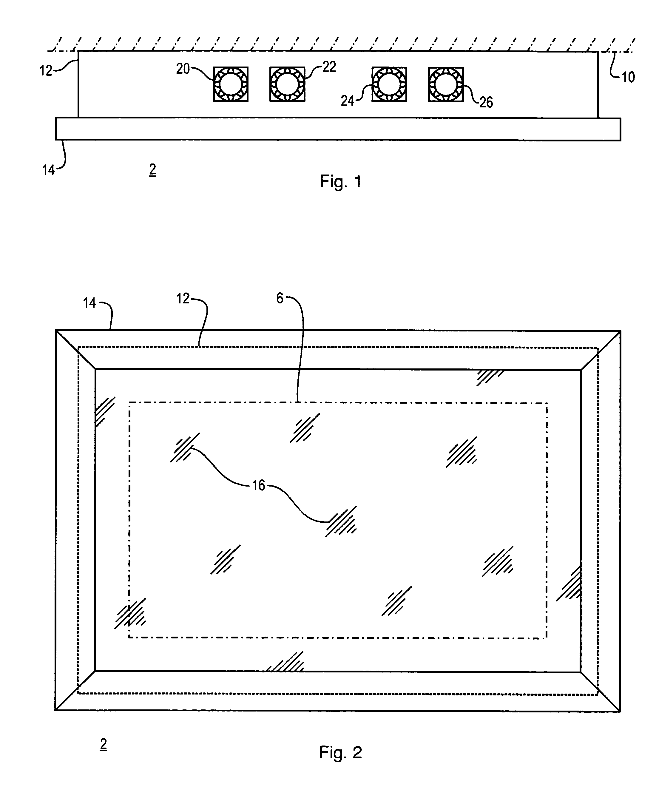
[0011]The present invention also teaches a method of concealing a light emitting video display that is mounted to a vertical surface. The method includes the steps of positioning a perimeter structure with a front opening adjacent to the vertical surface and about the video display, thereby enabling visual access to the video display through the front opening. Also, the steps of covering the front opening with a beam-split film and transmitting a portion of the light emitted by the video display during operation through the beam-split film. Then, reflecting a portion of the ambient light incident on the beam-split film, thereby concealing the video display when not in operation, and, circulating air through a light baffle disposed about the perimeter structure and adjacent to the video display with a fan, thereby enabling air cooling of the video display.
[0012]In a specific embodiment, the method includes the further step of depositing the beam-split film on a glass substrate. The method may also include the further steps of supporting the glass substrate with a decorative frame and positioning the decorative frame about the front opening. In a refinement, the step exhausting the air from the top of the perimeter structure with the fan is added. The fan may be operated at reduced speed, thereby enabling quiet operation. The fan may be energized at a predetermined temperature. In a specific embodiment, the method includes the further steps of operating the fan at a reduced speed upon detection of a first predetermined temperature, and, operating the fan at full speed upon detection of a second predetermined temperature.

Problems solved by technology

However, when the television or display is not active, the appearance of the blank screen is not aesthetically pleasing.
This undesirable aspect of flat panel televisions and displays increases in proportion to the size of the viewable area of the display.
The presence of a large flat panel television or display is desirable while such a device is active, however, when not active, the large blank screen can interfere with an intended decor.
However, concealment can be problematic in that it can interfere with access to the television or display when needed, and, concealment can interfere with the proper ventilation and cooling during operation of the device.
It can also be cumbersome to reveal and conceal such items from time to time, as it is needed for viewing.

Method used


Image

  • Mirrored decorative video display concealment and cooling apparatus and method
  • Mirrored decorative video display concealment and cooling apparatus and method
  • Mirrored decorative video display concealment and cooling apparatus and method

Examples


Embodiment Construction

[0025]Illustrative embodiments and exemplary applications will now be described with reference to the accompanying drawings to disclose the advantageous teachings of the present invention.

[0026]While the present invention is described herein with reference to illustrative embodiments for particular applications, it should be understood that the invention is not limited thereto. Those having ordinary skill in the art and access to the teachings provided herein will recognize additional modifications, applications, and embodiments within the scope thereof and additional fields in which the present invention would be of significant utility.

[0027]The present invention advances the art in the area of decorative concealment of video displays, including televisions, flat panel televisions, computer monitors, flat panel computer monitors, still-photo active displays, and generally, all kinds of video and image displays which function by emitting light for viewing by a user. Hereinafter, gen...


PUM


Abstract

An apparatus for concealing a light emitting video display mounted to a vertical surface by reflecting incident ambient light in mirror-like fashion. The apparatus includes a perimeter structure, which is positioned adjacent to the vertical surface about the video display. The perimeter structure has a front opening for enabling visual access to the video display. A beam-split film is disposed within the front opening, and has the characteristics of partial transmission of the light emitted by the video display and partial reflection of the incident ambient light. A fan is disposed to circulate air adjacent to the video display, and a light baffle is disposed about the perimeter structure for enabling circulation of ambient air through the perimeter structure while preventing the transmission of ambient light into the perimeter structure.

Description

BACKGROUND OF THE INVENTION[0001]1. Field of the Invention[0002]The present invention relates to video display concealment. More specifically, the present invention relates to a decorative apparatus and method for concealing a flat panel video display, which employs a one-way mirror and with forced ventilation cooling.[0003]2. Description of the Related Art[0004]Flat panel televisions and displays are becoming increasingly common, and will gradually replace virtually all cathode ray tube televisions and displays. Flat panel televisions and displays are frequently hung on a wall, in a fashion reminiscent of paintings and photographs. During the time when a television or display is turned on and active, this techniques works quite satisfactory because the flat panel display is viewed in a manner similar to viewing a painting or photograph. However, when the television or display is not active, the appearance of the blank screen is not aesthetically pleasing. The blank display screen r...

Claims


Application Information

Patent Timeline
Patent Type & Authority Patents(United States)
IPC IPC(8): G09G5/00G06F1/16H05K7/20
CPCG06F1/20G06F1/1601Y10S345/905
Inventor GRAHAM, JONATHAN W.
Owner GRAHAM JONATHAN W
Learn More