Multi-source fuel system for variable pressure injection

a fuel system and variable pressure technology, applied in the field of fuel systems, can solve the problems of increasing the complexity of the fuel injector, limiting the ability to shape,

Inactive Publication Date: 2008-07-15
CATERPILLAR INC
View PDF52 Cites 11 Cited by
  • Summary
  • Abstract
  • Description
  • Claims
  • Application Information

AI Technical Summary

Problems solved by technology

Although the fuel injection system of the '673 publication may adequately supply fuel to an engine at different pressures, it may, however, have limitations.
This dependency may limit the ability to shape the rate of fuel injections with the system of the '673 publication.
In addition, the intensifier component within each fuel injector may increase the complexity of the fuel injector and the associated overall system cost.

Method used


Image

  • Multi-source fuel system for variable pressure injection
  • Multi-source fuel system for variable pressure injection
  • Multi-source fuel system for variable pressure injection

Examples


Embodiment Construction

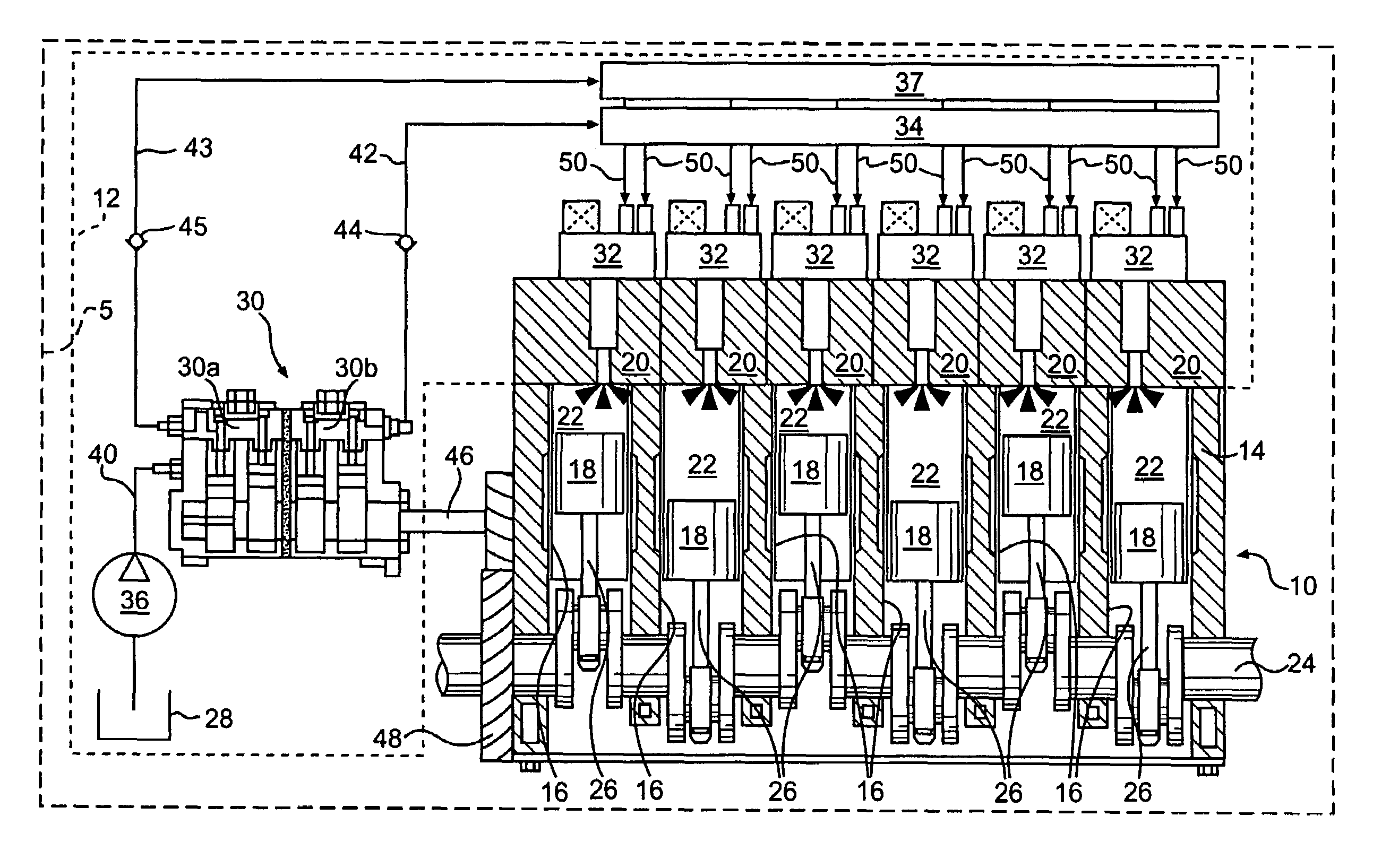
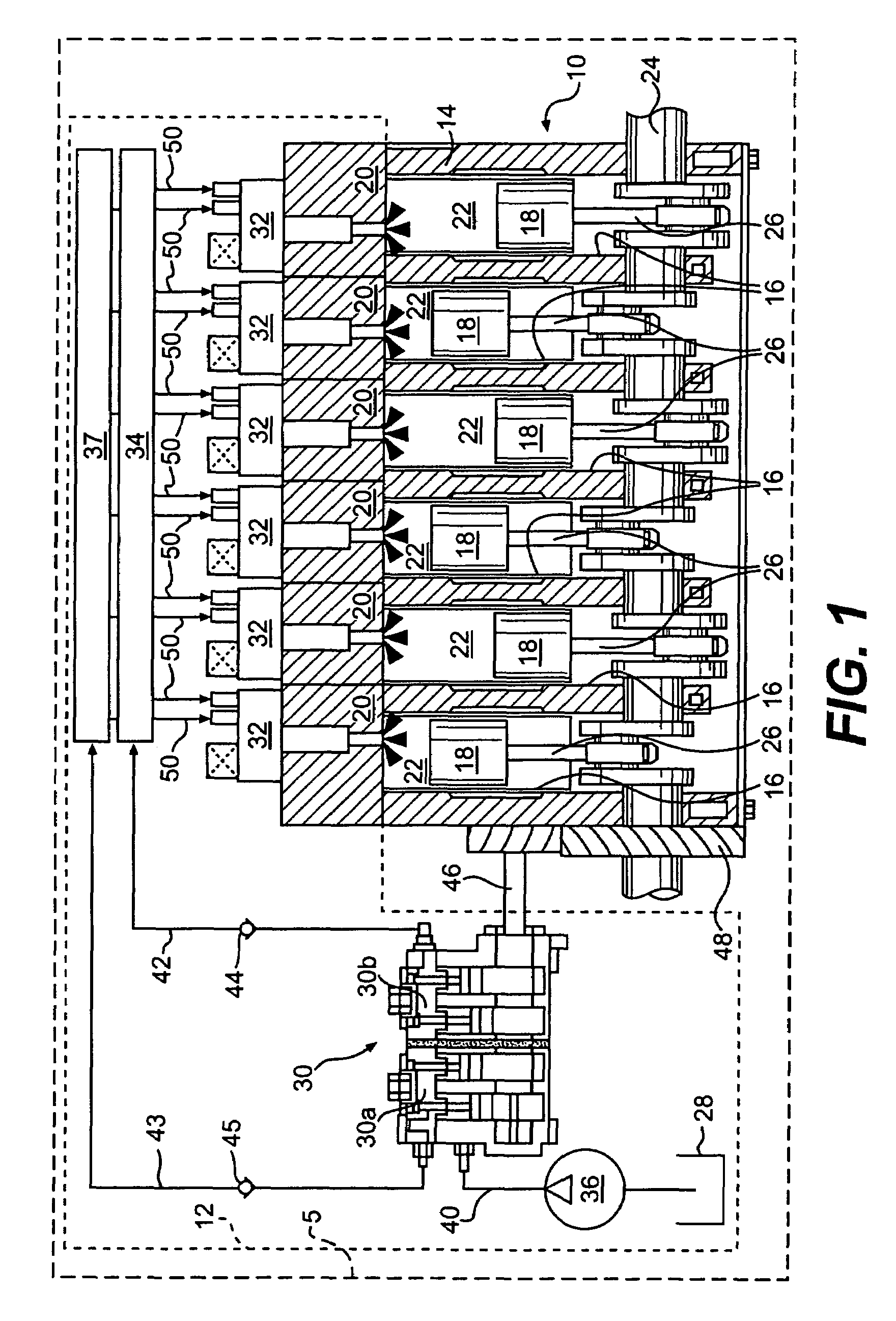
[0013]FIG. 1 illustrates a work machine 5 having an engine 10 and an exemplary embodiment of a fuel system 12. Work machine 5 may be a fixed or mobile machine that performs some type of operation associated with an industry such as mining, construction, farming, power generation, transportation, or any other industry known in the art. For example, work machine 5 may embody an earth moving machine, a generator set, a pump, or any other suitable operation-performing work machine.

[0014]For the purposes of this disclosure, engine 10 is depicted and described as a four-stroke diesel engine. One skilled in the art will recognize, however, that engine 10 may embody any other type of internal combustion engine such as, for example, a gasoline or a gaseous fuel-powered engine. Engine 10 may include an engine block 14 that defines a plurality of cylinders 16, a piston 18 slidably disposed within each cylinder 16, and a cylinder head 20 associated with each cylinder 16.

[0015]Cylinder 16, pisto...


PUM


Abstract

A fuel system for a work machine is disclosed. The fuel system has a fuel injector, a first source of fuel at a first pressure, a second source of fuel at a second pressure, and a pressure control device. The pressure control device is disposed between the fuel injector and the first and second sources. The pressure control device is configured to selectively direct the fuel at the first pressure and the fuel at the second pressure to the fuel injector.

Description

RELATED APPLICATIONS[0001]This application is based on and claims the benefit of priority from U.S. Provisional Application No. 60 / 734,784 by Dennis H. GIBSON, Jinhui SUN, and Mark F. SOMMARS, filed Nov. 9, 2005, the contents of which are expressly incorporated herein by reference.TECHNICAL FIELD[0002]The present disclosure is directed to a fuel system and, more particularly, to a fuel system having multiple sources of pressurized fuel for providing variable pressure injection events.BACKGROUND[0003]Common rail fuel systems provide a way to introduce fuel into the combustion chambers of an engine. Typical common rail fuel systems include an injector having an actuating solenoid that opens a fuel nozzle when the solenoid is energized. Fuel is then injected into the combustion chamber as a function of the time period during which the solenoid remains energized and the pressure of fuel supplied to the fuel injector nozzle during that time period.[0004]To optimize engine performance an...

Claims


Application Information

Patent Timeline
Patent Type & Authority Patents(United States)
IPC IPC(8): F02M63/00
CPCF02M45/04F02M47/027F02M63/0045F02M63/0225F02M63/0026F02M2200/40
Inventor GIBSON, DENNIS H.SOMMARS, MARK F.SUN, JINHUI
Owner CATERPILLAR INC
Why Eureka
Try Eureka