Conveying device

a technology of conveying device and conveyor, which is applied in the direction of conveyor, conveyor, transportation and packaging, etc., to achieve the effect of convenient handling, light weight and flexibleness

Active Publication Date: 2008-07-15
VESTERGAARD MARTIN
View PDF21 Cites 62 Cited by
  • Summary
  • Abstract
  • Description
  • Claims
  • Application Information

AI Technical Summary

Benefits of technology

[0008]The present invention, however, therefore sets out to provide a conveyor system which is very flexible such that it for example may be arranged on top of one or more layers of items, which furthermore comprise compulsion means for rotating the rollers such that the heavy work of pushing a number of items, for example luggage, through the cargo hold is avoided, and at the same time is very flexible and light-weight such that it is easy for the personnel to handle.

Problems solved by technology

Furthermore, by providing drive means to at least some of the transport rollers, it is unnecessary for the persons handling the cargo to push the cargo along the conveyor.

Method used


Image

  • Conveying device
  • Conveying device
  • Conveying device

Examples


Embodiment Construction

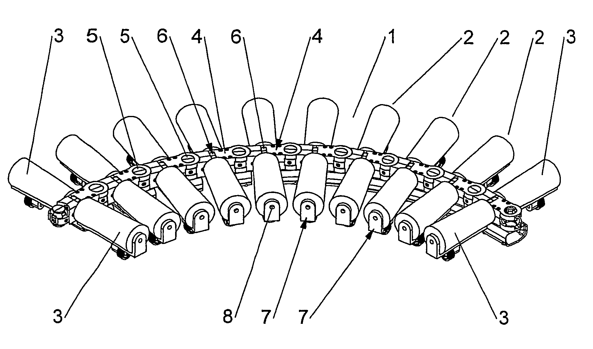
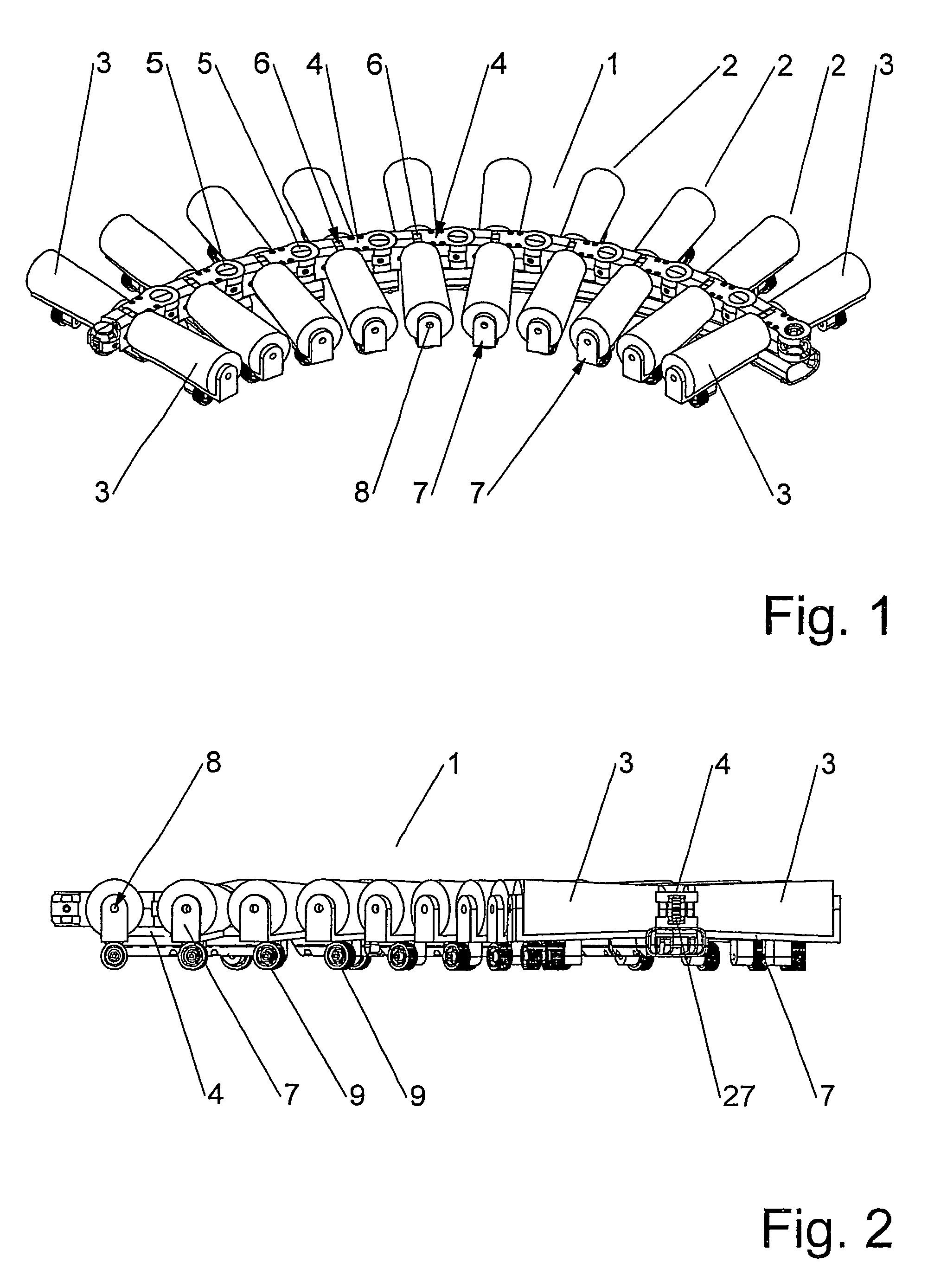
[0055]In FIGS. 1 and 2 is illustrated an embodiment of the invention wherein a conveying device 1 comprises a number of conveying elements 2.

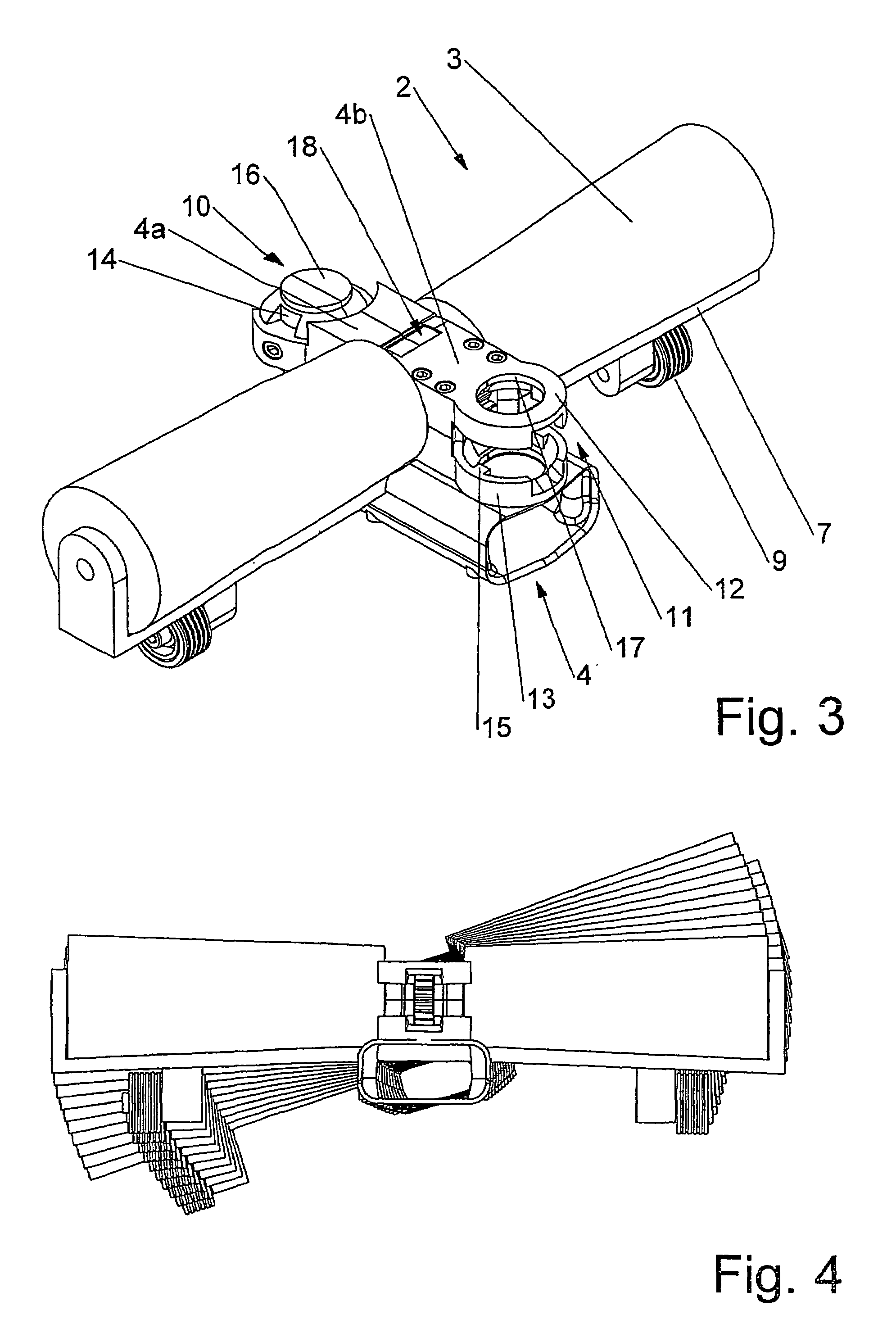
[0056]Each conveying element 2 comprises two transport rollers 3 and a chain box element 4. The conveying elements 2 are assembled in articulate manner to a neighbouring conveying element by the articulate joint 5, which will be further described with reference to FIG. 6.

[0057]Each chain box element further comprises a hinge mechanism 6 which makes it possible to incline, respectively decline, the gradient of the conveying device.

[0058]The conveying device is furthermore supplied with support structures 7. The support structure serves to relieve the chain box element of some of the stresses and loads arising when items are conveyed on the transport rollers in that the transport rollers are, in addition to being supported in the chain box element, also supported by a bearing structure 8 provided in the support structure 7.

[0059]In this particula...


PUM


Abstract

A conveying device (1) which is particular in that the conveying device comprises a plurality of conveying elements (2), where each conveying element (2) comprises a chain box element (4) in which at least one transport roller (3) is rotatably fixed such that rollers (3) arranged in adjacent conveying elements (2) define the conveying device transport plane, and that chain box elements (4) of adjacent conveying elements are interconnected in such a way that one conveying element may articulate in relation to adjacent conveying elements, and that at least some of the chain box elements in the conveying device comprise drive elements directly engaging and rotating the transport rollers (3).

Description

[0001]This application claims the benefit of PCT / DK2004 / 000065 filed Jan. 30, 2004 which is hereby incorporated by reference in its entirety.BACKGROUND OF THE INVENTION[0002]The present invention relates to a conveying device for conveying item, goods, luggage, parcels or the like as well as the use of such a device.[0003]Handling of goods, parcels, luggage and the like can be a very demanding task for a number of reasons, depending especially on the situation at hand. Personnel loading or unloading such items often have to lift them onto a conveyor, or carry the items to the conveyor in order for the conveyor to be able to transport them into or out of storage. In storage facilities, such as warehouses, trucks and containers, although the work may be heavy, the position of the people carrying out the task may be relatively comfortable and, furthermore, wheeled vehicles such as fork lifts and the like may in some instances be used in order to carry and move the items about.[0004]In ...

Claims


Application Information

Patent Timeline
Patent Type & Authority Patents(United States)
IPC IPC(8): B65G21/14B65G13/04B65G13/12
CPCB65G13/04B65G13/12B65G2201/025B65G2201/0264
Inventor VESTERGAARD, MARTIN
Owner VESTERGAARD MARTIN
Why Eureka
Try Eureka