Electric fishing reel

a technology of electric fishing reels and reels, which is applied in the direction of reels, applications, fishing, etc., can solve the problems of damage to the power transmission gear, and inability to quickly reel out fishing line with the terminal tackle, so as to improve the rotation performance at the time of manual winding operation, reduce noise (sound) at the time of driving the motor, and smooth winding operation

Inactive Publication Date: 2008-07-15
DAIWA SEIKO CORPORATION
View PDF9 Cites 12 Cited by
  • Summary
  • Abstract
  • Description
  • Claims
  • Application Information

AI Technical Summary

Benefits of technology

[0008]The present invention has been devised on the basis of the above-described problems, and its object is to provide an electric fishing reel which is capable of attaining silencing during the winding drive of the spool by the drive motor and of carrying out light clutch switching operation.
[0045]According to the above-described construction, when the spool is switched from the power transmitting state to the power cutoff state by the clutch mechanism, the clutch actuating member rotationally locked so as to be movable in the axial direction with respect to the rotor is axially moved, and separated from the retaining portion integrally rotatable with the spool. A rotational load from the rotor which is a part of the power transmission does not act on the clutch actuating member and moved in the axial direction. Therefore, the switching operation of the clutch mechanism can be performed comfortably.
[0047]According to the above-described construction, when switching from the power transmitting state to the power cutoff state by the clutch mechanism, the clutch actuating member, which is fitted in and rotationally locked axially movably to the second rotor to which power is transmitted from the drive motor side through the first rotor and the belt, is moved in the axial direction and is disengaged from the retaining portion which is rotated integrally with the spool. For this reason, the clutch actuating member axially slides without a rotational load being applied thereto from the second rotor which is a power transmitting portion, so that the switching operation of the clutch mechanism can be performed lightly. In addition, since the construction provided is such that the power transmission between the first rotor and the second rotor is effected not by the meshing of gears but by means of the belt, tooth faces are not damaged during the actuation of the clutch mechanism, and silencing during driving can be accomplished.
[0049]According to the invention, it is possible to obtain an electric fishing reel which is capable of attaining silencing during the winding drive of the spool by the drive motor and of carrying out light clutch switching operation.
[0050]According to the above-describe construction, the rotational driving force by the drive motor is transmitted to the spool through the belt wound around the first rotor and the second rotor. Therefore, noise (sound) at the time of driving the motor can be reduced. Further, the driving force by the manual handle is transmitted to the spool through the first rotor, the second rotor and the belt wound around it. Therefore, comparing with the power transmission by the mesh between the general gears, large mesh amount (wound length of the belt with respect to each rotor) can be secured, and there is no influence of the damage, the deformation and the like on a gear surface of the gear, thereby the rotation performance at the time of manual winding operation can be improved and smooth winding operation is achieved.

Problems solved by technology

In the electric fishing reel, since a planetary gear mechanism having planetary gears is interposed in the power transmission route of the spool, even if the clutch mechanism is switched over (clutch OFF) to the fishing line releasing state (spool free state), some gears of such as the planetary gears are rotated together with the spool in an interlocked manner, so that the rolling frictional resistance due to the meshing of gears is generated, resulting in inferior freely reeling-out performance.
Hence, a problem remains that the fishing line with the terminal tackle cannot be reeled out speedily.
Therefore, there are problems in that damage is possibly caused to the power transmission gear, and the meshing driving noise becomes large.
In addition, since terminal tackle including a sinker having some weight is attached to a fishing line, the load in the rotating direction on the mutually meshing gears becomes disadvantageously large, so that it becomes difficult to switch the clutch from ON to OFF.
However, if consideration is given to the ease of disengaging the clutch (ease in axial movement of the power transmission gear), the helical gears cannot be used.
In this case, even if helical gears are used, if satisfactory clutch operability is taken into consideration, the helix angle of the tooth trace cannot be made large, so that there is a limit to the improvement of the meshing performance.

Method used


Image

  • Electric fishing reel
  • Electric fishing reel
  • Electric fishing reel

Examples


Embodiment Construction

[0056]Referring to the accompanying drawings, a description will be given of an embodiment of the present invention.

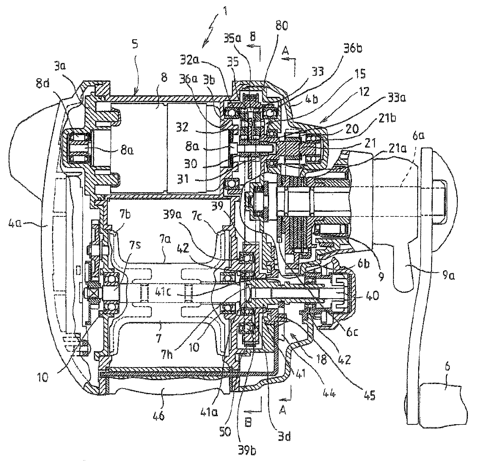
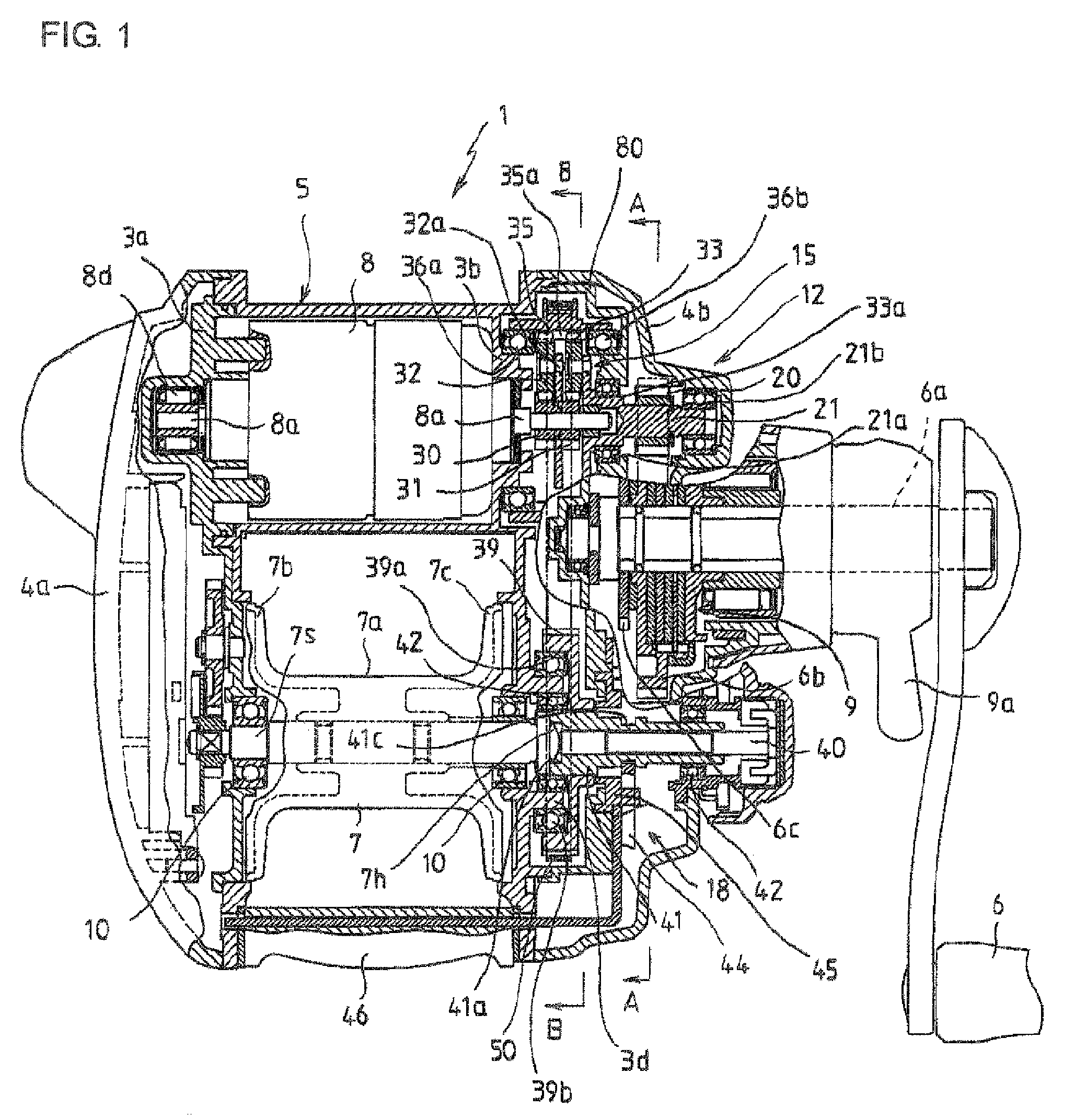
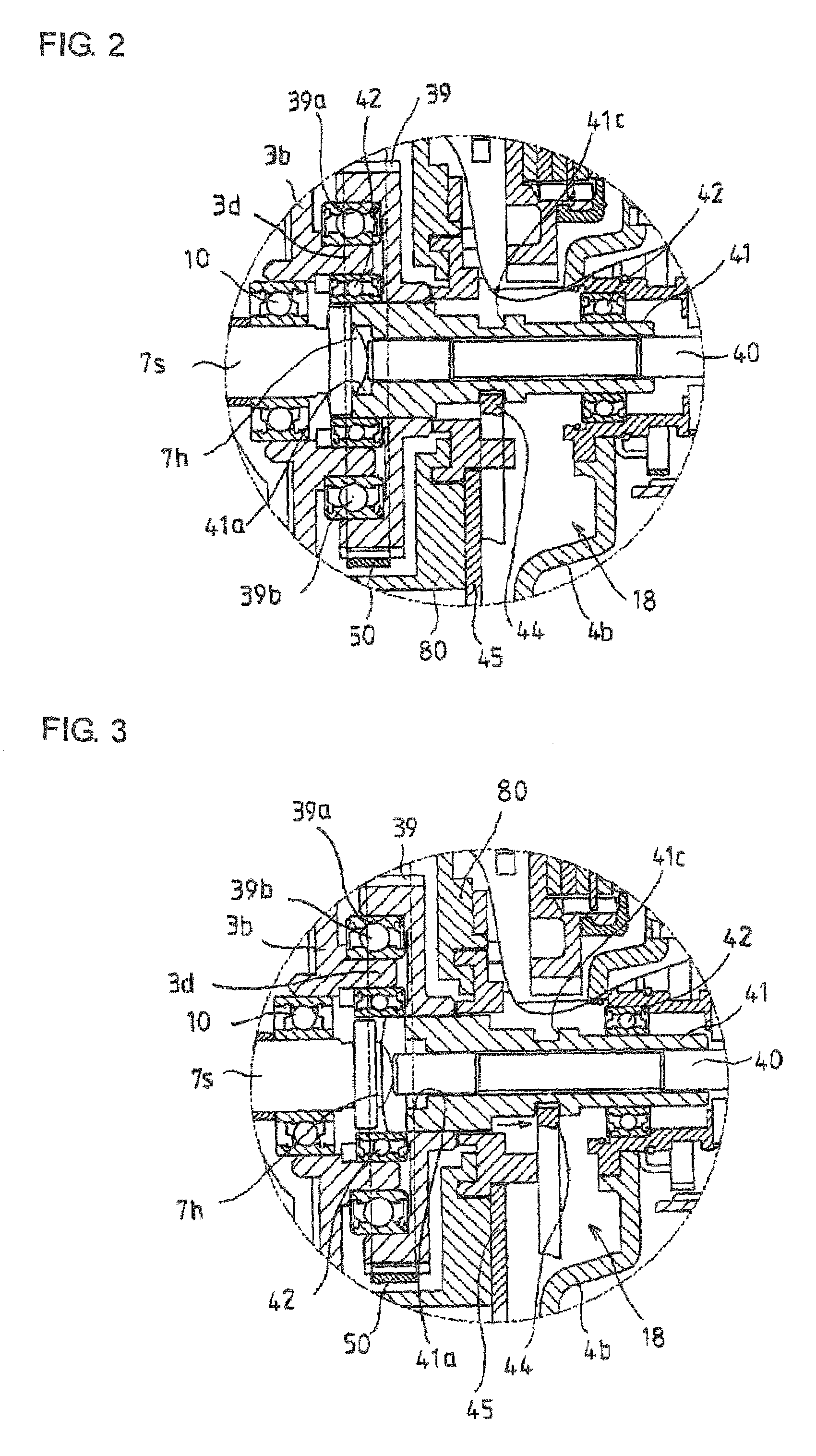
[0057]FIGS. 1 to 5 show an embodiment of an electric fishing reel in accordance with the invention. FIG. 1 is a plan view illustrating an internal structure. FIGS. 2 and 3 are enlarged diagrams illustrating essential portions shown in FIG. 1, in which FIG. 2 is a diagram illustrating a power transmitting state (clutch ON), and FIG. 3 is a diagram illustrating a power cutoff state (clutch OFF). FIG. 4 is a partial cross-sectional view taken from a direction along line A-A in FIG. 1, and FIG. 5 is a partial cross-sectional view taken from a direction along line A-A in FIG. 1.

[0058]An electric fishing reel 1 has a reel body 5 constructed by attaching outer side plates 4a and 4b to left and right frames 3a and 3b, respectively. A manual handle 6, which is operated for winding, is provided on one side plate (right side plate 4b) making up the reel body 5. A spool 7 around w...


PUM


Abstract

An electric fishing reel has a power transmission mechanism for transmitting rotational driving force based on a drive motor and a manual handle to a spool; and a clutch mechanism for switching the power transmission mechanism between a power transmitting state and a power cutoff state. The power transmission mechanism includes a planetary gear mechanism disposed on the drive motor; a first rotor with which the planetary gear mesh; a second rotor which is driven and coupled to the first rotor through a belt; and a clutch actuating member fitted and rotationally locked in the second rotor to be movable in an axial direction and is moved in the axial direction. An engaging portion of the clutch actuating member is capable of switching the power transmission mechanism between a power transmitting state and a power cutoff state by engaging with or disengaging from a retaining portion of the spool.

Description

BACKGROUND OF THE INVENTION[0001]The present invention relates to an electric fishing reel of a manual / electric compatible type which has a drive motor for rotationally driving a spool supported rotatably on a reel body and which winds and drives a spool by the rotative operation of a manual handle provided on one side of the reel body.[0002]Typically, an electric fishing reel is so constructed as to transmit the rotational driving force of a drive motor provided on a reel body to a spool through a planetary gear mechanism (reduction gear mechanism). Generally, a clutch mechanism for changing over the spool between a fishing line winding state and a fishing line releasing state (spool free state) is disposed in the power transmission route. In addition, the reel body is provided with a manual handle to allow not only the electrically powered driving using the drive motor but the winding drive of the spool by manual operation. The winding driving force applied by the manual handle is...

Claims


Application Information

Patent Timeline
Patent Type & Authority Patents(United States)
IPC IPC(8): A01K89/01
CPCA01K89/017
Inventor TERAUCHI, TAKASHIMURAKAMI, SHINJI
Owner DAIWA SEIKO CORPORATION
Why Eureka
Try Eureka