One-return wave equation migration

a one-return wave and equation technology, applied in the field of one-return wave equation migration, can solve the problems of large storage and memory capacity, computational cost, and inability to produce good images of the geologic structure that contains strong turning waves and duplex waves

Active Publication Date: 2008-07-15
LANDMARK GRAPHICS
View PDF5 Cites 28 Cited by
  • Summary
  • Abstract
  • Description
  • Claims
  • Application Information

AI Technical Summary

Problems solved by technology

It fails to produce good images of the geologic structure that contains strong turning waves and duplex waves, such as an overhanging salt boundary and geological structure with steep dip.
However, it is computationally expensive in that it demands huge storage and memory capabilities for large 3D datasets.
Reverse-time migration (Baysal, et al, “Reverse Time Migration,”Geophysics 48(11), 1514-1524, 1983; Biondi et al., Prestack “Imaging of Overturned Reflections by Reverse Time Migration”, Expanded Abstracts, SEG 72nd Annual Meeting 1284-1287, 2002) takes into account the turning waves, but it is usually computationally too expensive for

Method used


Image

  • One-return wave equation migration
  • One-return wave equation migration
  • One-return wave equation migration

Examples


Embodiment Construction

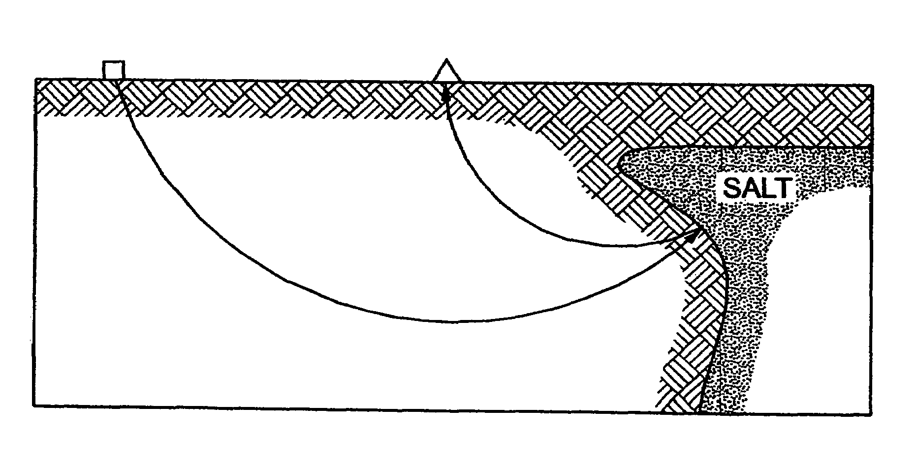
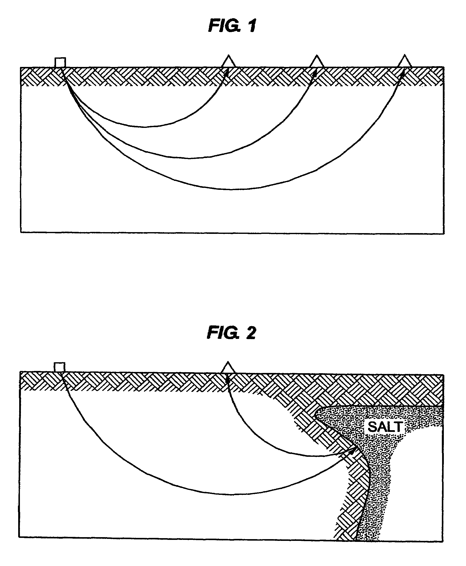
[0025]Turning waves are commonly recorded, at the surface, from a geologic structure where the velocity increases with depth. If the turning waves are not reflected from an interface with impedance contrast (FIG. 1), there's no contribution from the image of subsurface structure. If the turning waves occur before (or after) reflection from the interface, such as the overhanging salt flanks (FIG. 2) or vertical features, the turning waves may have a significant contribution to the image of such events.

[0026]In short-profile migration, a two-pass extrapolation, is used for both source and receiver wave fields. During the first-pass downward extrapolation, the turning wave energy at each depth z is saved for the second-pass extrapolation. The second-pass extrapolation reconstructs the contribution from the turning wave. We now obtain four volumes of wave field: PSD(x,y,z,ω); PSU(x,y,z,ω); PRD(x,y,z,ω); and PRU(x,y,z,ω), where ω is frequency and the subscripts S and R indicate source an...


PUM


Abstract

A one-return wave equation migration is used to extrapolate both down-going and up-going waves. Followed by a properly designed imaging condition, the partial image contributed form turning waves is correctly reconstructed. Numerical examples show that this method can significantly enhance definition of an overhanging salt boundary and a geological structure with vertical features.

Description

BACKGROUND OF THE INVENTION[0001]The Field of the Invention[0002]The present invention pertains a one-return wave equation migration to extrapolate both down-going and up-going waves. Followed by properly designed imaging conditions, the partial images contributed from turning waves and multiple reflections are correctly reconstructed. Numerical examples show that this method can significantly enhance the imaging of an overhanging salt boundary and vertical faults.[0003]The Prior Art[0004]Conventional one-way wave equation migration has been successfully and widely applied to 3D pre-stack depth imaging for years. This method recursively downward continues source and receiver wavefields independently. It handles primary reflections but ignores the turning waves that propagate beyond 90° and multiple reflections, such as duplex waves that describe propagation paths with a double reflection involving a reflecting base boundary and a near vertical feature. It fails to produce good image...

Claims


Application Information

Patent Timeline
IPC IPC(8): G01V1/36
CPCG01V1/28G01V2210/51
Inventor JIN, SHENGWENXU, SHIYONG
Owner LANDMARK GRAPHICS
Why Eureka
Try Eureka