X-ray generator and X-ray CT apparatus comprising same
a technology of generating device and ct apparatus, which is applied in the direction of x-ray apparatus, electrical apparatus, etc., can solve the problems of large x-ray device, inability to perform above adjustment, and large x-ray device size, so as to reduce both unbalance voltage and increase the reduction effect , the effect of large permeability
- Summary
- Abstract
- Description
- Claims
- Application Information
AI Technical Summary
Benefits of technology
Problems solved by technology
Method used
Image
Examples
embodiment 1
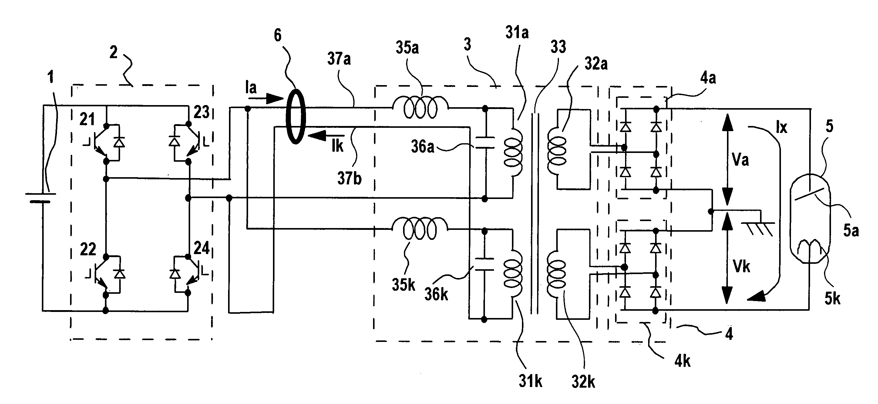
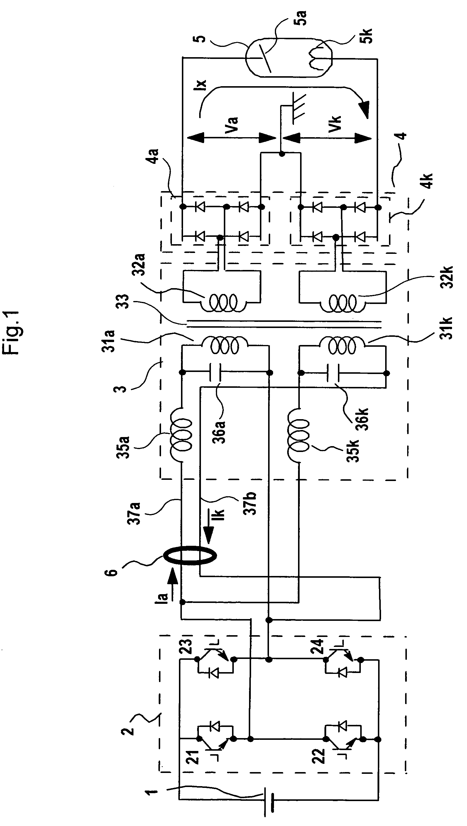
[0046]In this embodiment, an X-ray high voltage device which can remove the unbalance voltage due to (1) difference in impedance of a high voltage transformer mentioned in the section of the background technique will be described.
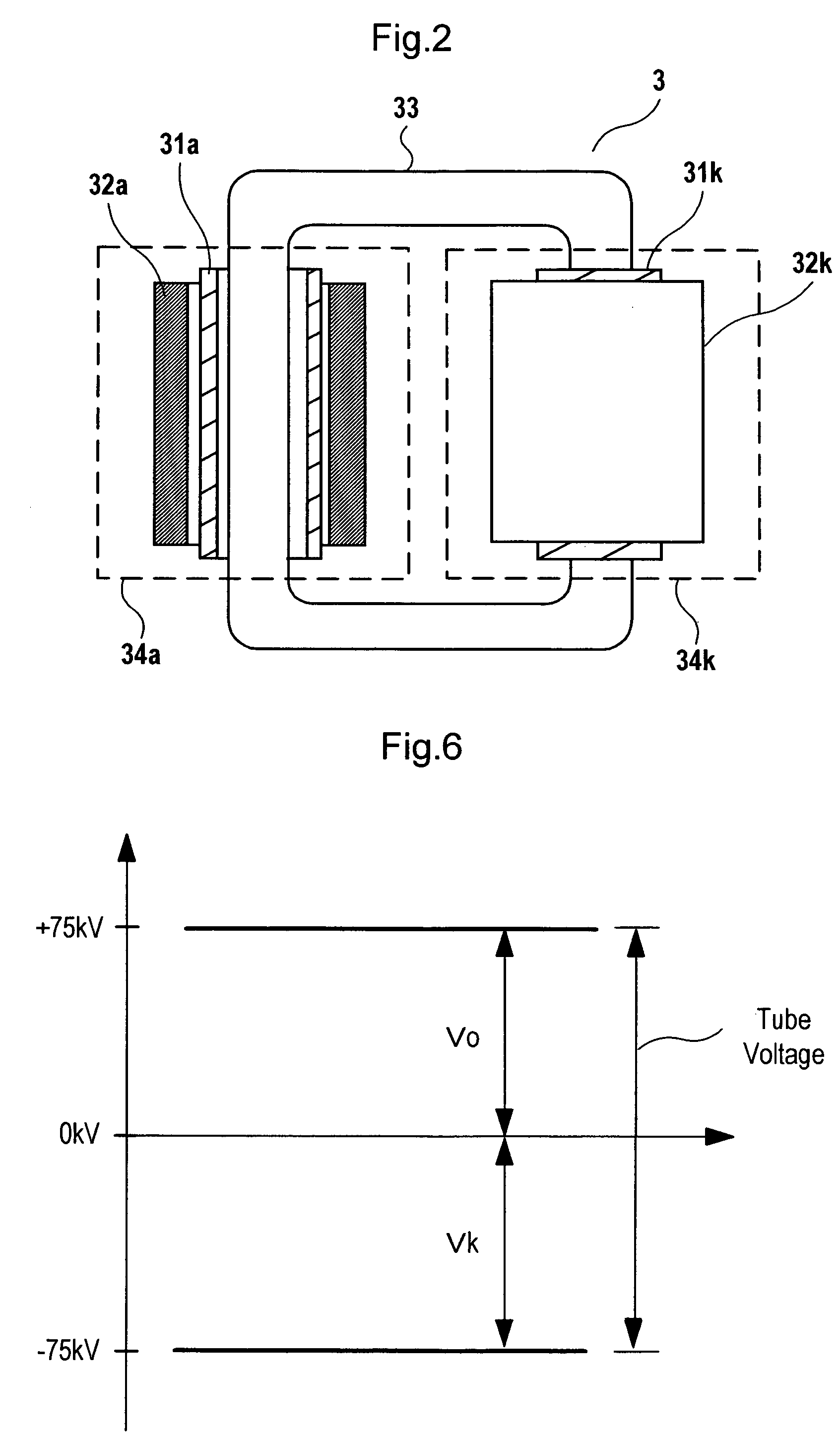
[0047]The reason of generation of the difference between Va and Vk (hereinafter referred to as “unbalance voltage”) due to the difference in impedance of the high voltage transformer mentioned at (1) will be analyzed, then solving means will be subsequently described. FIG. 9 shows an X-ray generator using a metal X-ray tube. In this high voltage transformer 3, because voltage difference between secondary windings 3c and 3d on a high voltage side and primary windings 3a and 3b on a low voltage side is very large, primary windings 3a and 3b and secondary windings 3c and 3d are detached at a predetermined distance and an insulator is inserted therebetween. A part of generated magnetic flux passes through between primary windings 3a and 3b and secondary winding...
embodiment 2
[0083]In this embodiment, an X-ray high voltage device will be described in which the unbalance voltage due to (1) the difference in impedance of high voltage transformer described in the section of the background technique and in Embodiment 1 can be removed. FIG. 3 is a schematic diagram of an inverter-type X-ray high voltage device according to Embodiment 2, a main object of which is to remove the unbalance voltage generated due to impedance difference in the high voltage transformer. Similarly to Embodiment 1, the X-ray tube according to Embodiment 2 may be either a glass X-ray tube or a metal X-ray tube. FIG. 3 shows the case of the glass X-ray tube as in FIG. 1.
[0084]According to Embodiment 2, the secondary windings of high voltage transformer 3 and high voltage rectifier 4 are further divided than in Embodiment 1 shown in FIG. 1, wherein first secondary windings of the high voltage transformer is divided into 32a1 and 32a2, second secondary windings 32k is divided into 32k1 an...
embodiment 3
[0092]In Embodiment 3, an X-ray high voltage device which can remove the unbalance voltage due to both the difference in impedance of the high voltage transformer described at (1) and the difference in load impedance described at (2) will be described. Since analysis of (1) generation of impedance of the high voltage transformer is described in Embodiment 1, the reason of (2) generation of the difference between Va and Vk (hereinafter referred to as “unbalance voltage”) due to difference in impedance of the high voltage transformer will be analyzed and means for solving (1) and (2) according to this embodiment will be subsequently described.
[0093]The unbalance voltage due to (2) the difference in load impedance is generated in an inverter-type X-ray high voltage device using a metal X-ray tube, a part of a container of which is made of metal and grounded to the earth. As shown in FIG. 12, first high voltage rectifier 4a is connected with anode 5a ′ of X-ray tube 5′ and second high v...
PUM
 Abstract
Description
Claims
Application Information
 - R&D
- Intellectual Property
- Life Sciences
- Materials
- Tech Scout
- Unparalleled Data Quality
- Higher Quality Content
- 60% Fewer Hallucinations
Browse by: Latest US Patents, China's latest patents, Technical Efficacy Thesaurus, Application Domain, Technology Topic, Popular Technical Reports.
© 2025 PatSnap. All rights reserved.Legal|Privacy policy|Modern Slavery Act Transparency Statement|Sitemap|About US| Contact US: help@patsnap.com


