Multi-step electric connector

a multi-step, electric connector technology, applied in the direction of coupling device connection, two-part coupling device, electrical apparatus, etc., can solve the problems of more prominent errors and created impedance characteristics, and achieve the effect of maximizing spa

Inactive Publication Date: 2008-07-22
FCI ASIA PTE LTD
View PDF10 Cites 14 Cited by
  • Summary
  • Abstract
  • Description
  • Claims
  • Application Information

AI Technical Summary

Benefits of technology

[0013]The present invention is a configuration effective for a connector having a multiple level type structure under a connector standard called the serial ATA standard which makes high-speed signal transfer possible. When each leg portion of the electric contact rows for signals of each level is connected to a board and the like, differences in length of each of the leg portions due to the differing levels, that is, errors in the impedance characteristics are created. These errors appear more prominently the higher the speed of the signal transferred. However, by having a shield portion connected to a grounding line, which at least partially covers the leg portion of each electric contact for signals, the impedance can be matched, that is, a uniform signal transfer characteristic is obtained and the reliability of signal transfer is improved.
[0015]If the aforementioned electric contacts for grounding of at least one of the levels are connected to the aforementioned shield portion, the electric connector according to the present invention makes integral formation possible, and the leg portions of each of the electric contacts for grounding can be eliminated, and space can be used more efficiently.
[0027]The aforementioned housing can be configured in an arbitrary shape capable of housing electric contacts and at the same time anchor and hold mating electric contacts, and can be made in a shape for which the removing of the connector is done easily.
[0029]By anchoring the aforementioned housing on one portion of an open end of a board, connection with peripheral devices can be done easily without disassembling a personal computer and the like whereon a board is mounted.

Problems solved by technology

When each leg portion of the electric contact rows for signals of each level is connected to a board and the like, differences in length of each of the leg portions due to the differing levels, that is, errors in the impedance characteristics are created.
These errors appear more prominently the higher the speed of the signal transferred.

Method used


Image

  • Multi-step electric connector
  • Multi-step electric connector
  • Multi-step electric connector

Examples


Embodiment Construction

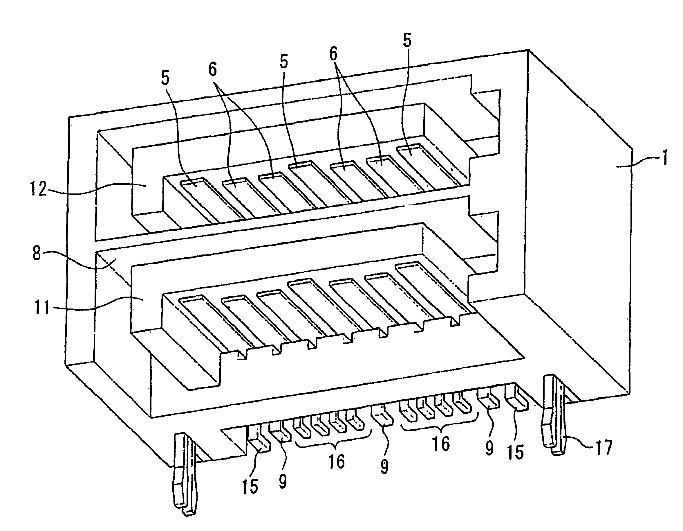
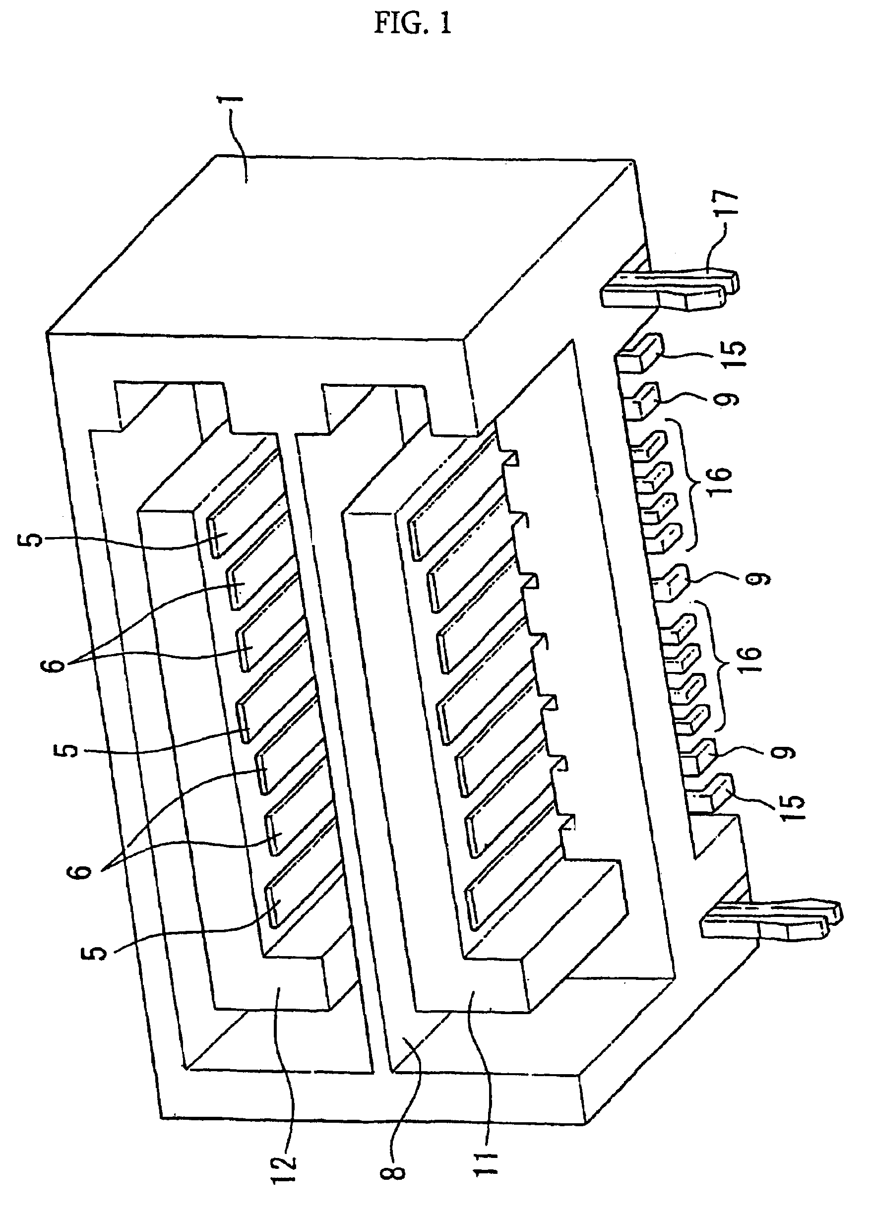
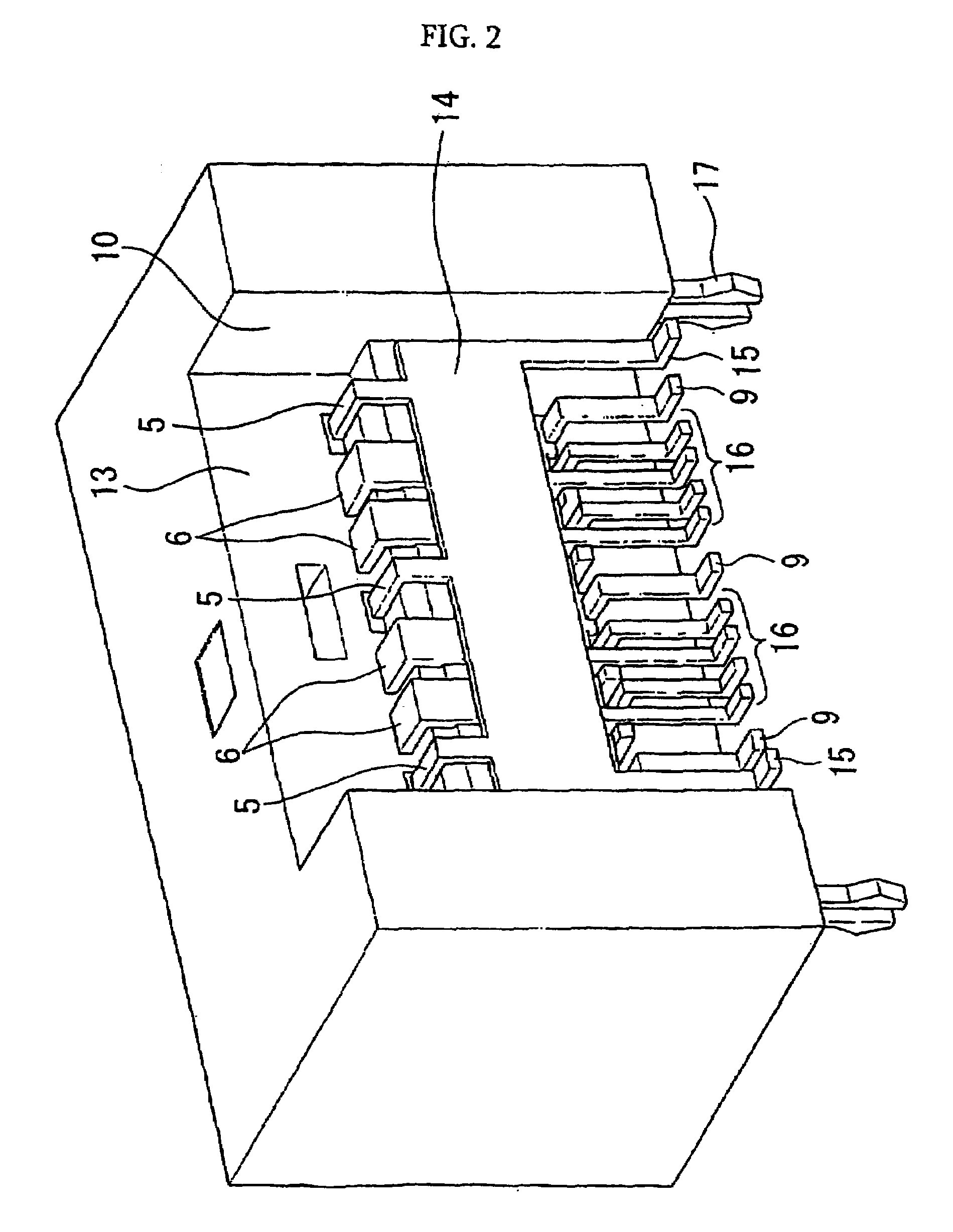
[0052]FIG. 1, FIG. 2, and FIG. 3 show perspective views of a two level type serial ATA standard electric connector.

[0053]FIG. 1 is a front perspective view of said electric connector. Said connector is constructed from a casing 1 molded from resin corresponding to the main body of the connector, a guide portion placed therein, and an electric contact row (see FIG. 4) aligned on the surface of the aforementioned guide portion.

[0054]The aforementioned casing 1 has an insertion slot side for inserting a mating connector (FIG. 1 front) and a connector back side (FIG. 2 front). On the inside of the casing, at said insertion slot side of FIG. 1, a space is formed that is divided in two by a boundary region portion 8 that extends in the direction of the back surface of the connector, and further, in order to fit with the main body of the paired connector, a guide portion 11 and guide portion 12 are provided. The aforementioned guide portion 11 protrudes from the back surface of the connect...


PUM


Abstract

The differences in length of conductor portions which arise due to differing levels in a two level type electric connector, that is, errors in the impedance characteristics, are improved. The multiple level type electric connector of the present invention is characterized by being provided with a plurality of levels of rows of electric contacts aligned on a same surface, stacked in a direction perpendicular to the aforementioned surfaces, each electric contact row containing electric contacts for signals and electric contacts for grounding, each of the electric contacts for signals contained in each of the electric contact rows having a free end located on a first plane differing for each level, and a leg portion extending downwards from said first plane and leading to a same second plane, and each of the electric contacts for grounding contained in each of the electric contact rows having a free end located on a first plane, and a leg portion extending downwards from said first plane and leading to a same second plane connected to a grounding line, and being provided with a shield portion connected to a grounding line, and at least partially covering the leg portions of the aforementioned electric contacts.

Description

TECHNICAL FIELD[0001]The present invention concerns an interface for high-speed communication, and more specifically concerns a connector for an end of a board for connecting a personal computer and a peripheral device.BACKGROUND ART[0002]In recent years, technical development in electronic device-related fields has been remarkable, and in particular, the improvement of speed in personal computers has been making extraordinary technical advancements. Japanese Unexamined Patent Publication No. 2001-143798 describes, concerning a connector standard (device bay) used for connecting electrically to personal computer peripheral devices, a connector wherein the portions connecting to a board of the leg portions of two levels of electrical contact rows are capable of being grounded along a straight line on a flat plane, and wherein a plurality of electric connector rows are housed while minimizing the size of the connector.[0003]In the two level type electric contact array disclosed in the...

Claims


Application Information

Patent Timeline
Patent Type & Authority Patents(United States)
IPC IPC(8): H01R13/60H01R13/658H01R12/72H01R13/6471H01R13/6474H01R13/6596H01R24/00
CPCH01R12/722H01R13/6596H01R13/6474H01R13/6471H01R13/648
Inventor SHINDO, HIDEHIRO
Owner FCI ASIA PTE LTD
Why Eureka
Try Eureka