Programmable radio frequency waveform generator for a synchrocyclotron

Active Publication Date: 2008-07-22
MEVION MEDICAL SYST
View PDF12 Cites 251 Cited by
  • Summary
  • Abstract
  • Description
  • Claims
  • Application Information

AI Technical Summary

Benefits of technology

[0012]This invention is intended to address the generation of the proper variable frequency and amplitude modulated signals for efficient injection into, acceleration by, and extraction of charged particles from an accelerator.

Problems solved by technology

Accurate and reproducible control of the frequency over the range required by a desired final energy that compensates for both relativistic mass increase and the dependency of magnetic field on the distance from the center of the dee has historically been a challenge.

Method used


Image

  • Programmable radio frequency waveform generator for a synchrocyclotron
  • Programmable radio frequency waveform generator for a synchrocyclotron
  • Programmable radio frequency waveform generator for a synchrocyclotron

Examples


Embodiment Construction

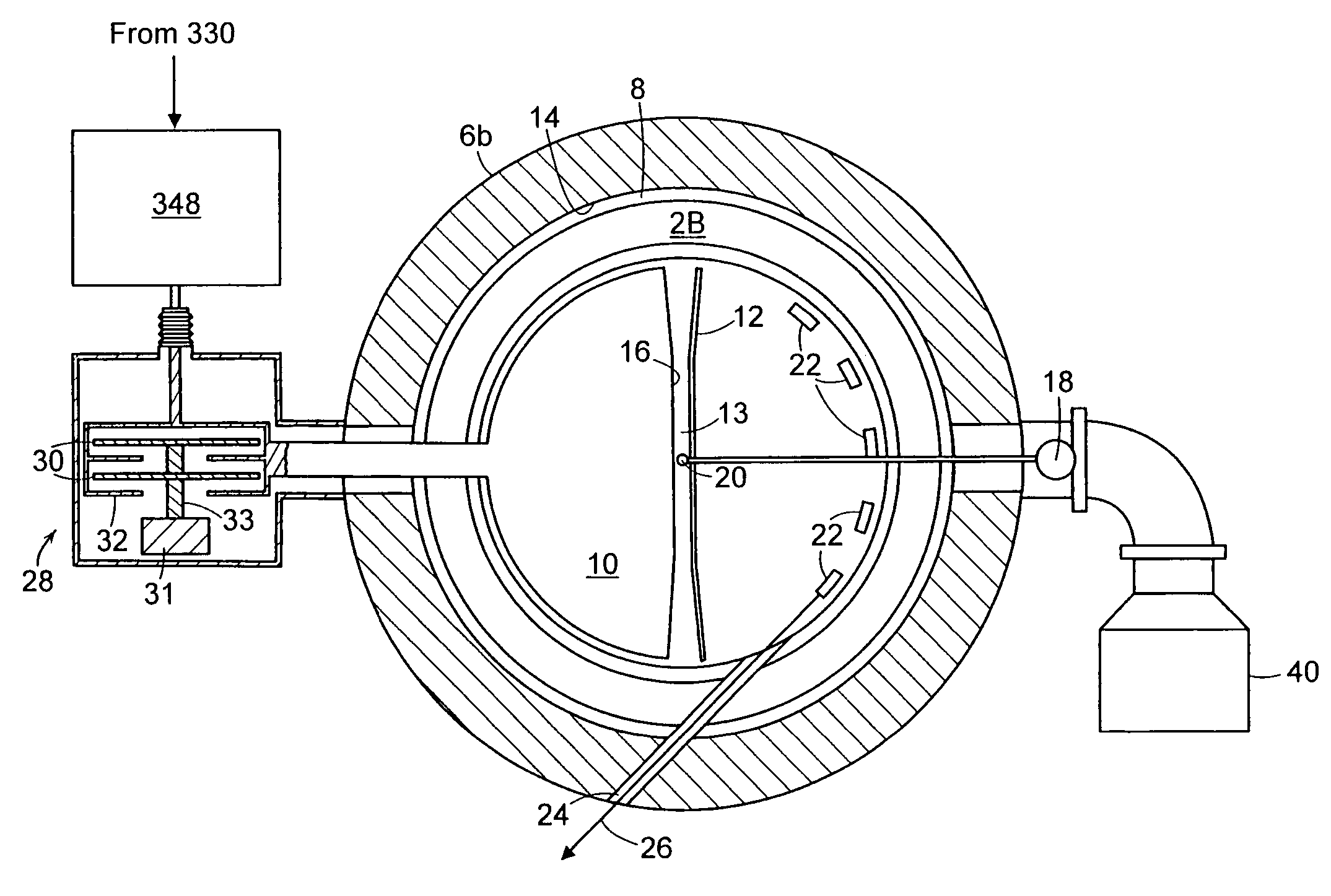
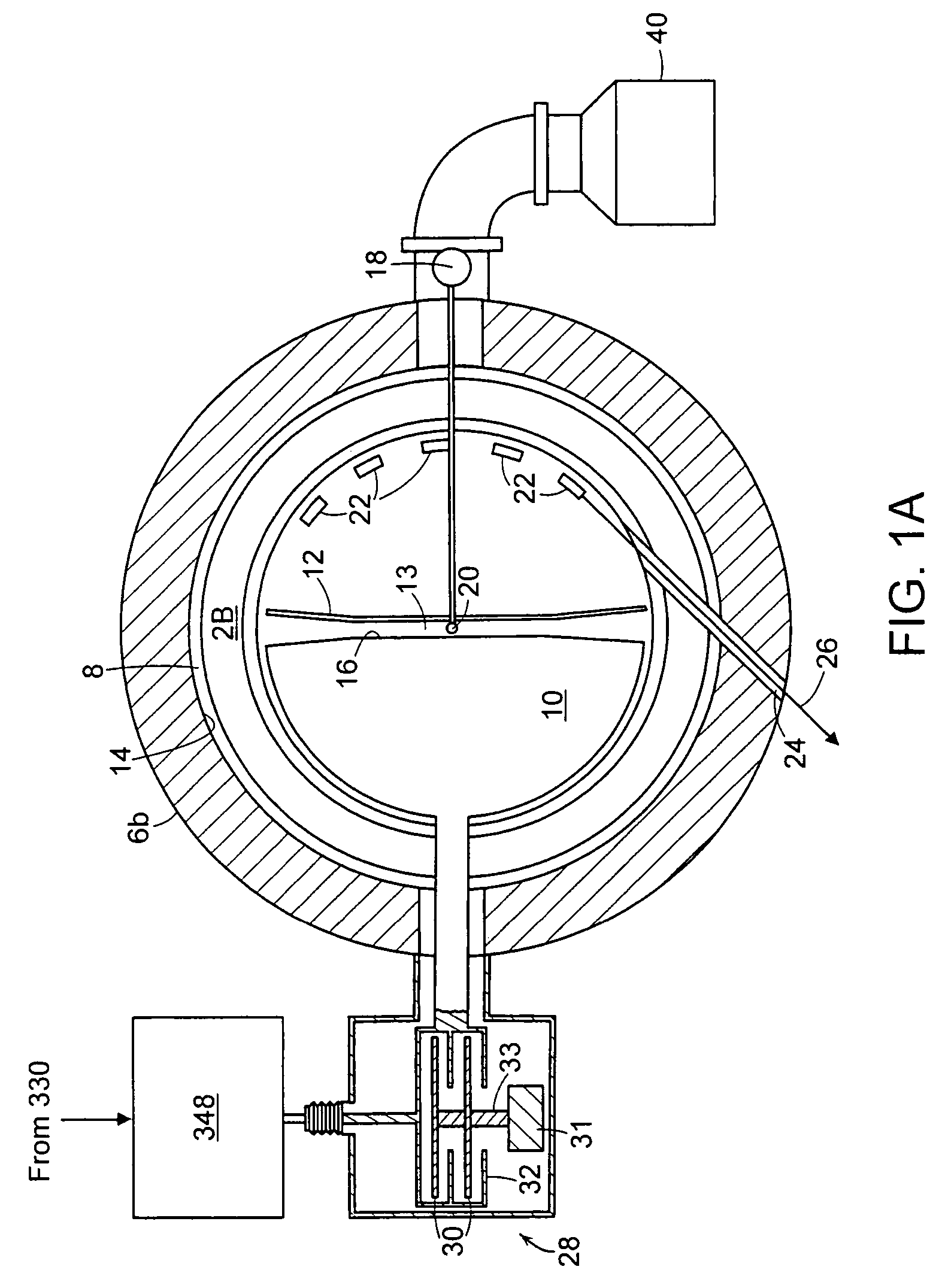
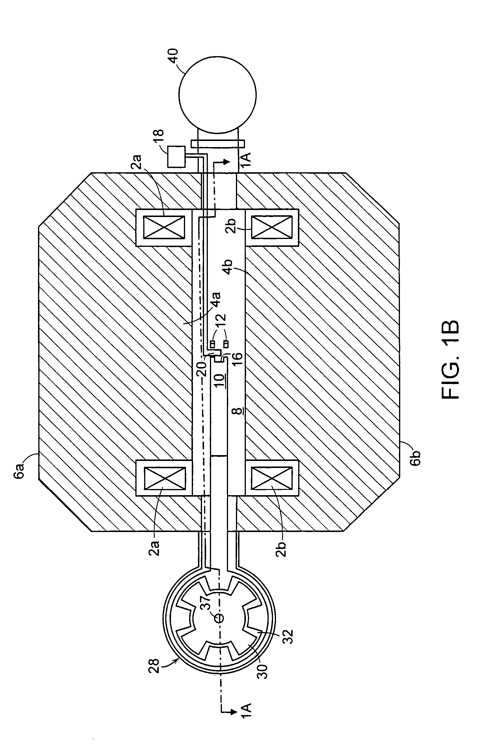
[0034]This invention relates to the devices and methods for generating the complex, precisely timed accelerating voltages across the “dee” gap in a synchrocyclotron. This invention comprises an apparatus and a method for driving the voltage across the “dee” gap by generating a specific waveform, where the amplitude, frequency and phase is controlled in such a manner as to create the most effective particle acceleration given the physical configuration of the individual accelerator, the magnetic field profile, and other variables that may or may not be known a priori. A synchrocyclotron needs a decreasing magnetic field in order to maintain focusing of the particles beam, thereby modifying the desired shape of the frequency sweep. There are predictable finite propagation delays of the applied electrical signal to the effective point on the dee where the accelerating particle bunch experiences the electric field that leads to continuous acceleration. The amplifier used to amplify the ...


PUM


Abstract

A synchrocyclotron comprises a resonant circuit that includes electrodes having a gap therebetween across the magnetic field. An oscillating voltage input, having a variable amplitude and frequency determined by a programmable digital waveform generator generates an oscillating electric field across the gap. The synchrocyclotron can include a variable capacitor in circuit with the electrodes to vary the resonant frequency. The synchrocyclotron can further include an injection electrode and an extraction electrode having voltages controlled by the programmable digital waveform generator. The synchrocyclotron can further include a beam monitor. The synchrocyclotron can detect resonant conditions in the resonant circuit by measuring the voltage and or current in the resonant circuit, driven by the input voltage, and adjust the capacitance of the variable capacitor or the frequency of the input voltage to maintain the resonant conditions. The programmable waveform generator can adjust at least one of the oscillating voltage input, the voltage on the injection electrode and the voltage on the extraction electrode according to beam intensity and in response to changes in resonant conditions.

Description

RELATED APPLICATIONS[0001]This application is a continuation of U.S. application Ser. No. 11 / 187,633, filed Jul. 21, 2005, now abandoned which claims the benefit of U.S. Provisional Application No. 60 / 590,089, filed on Jul. 21, 2004. The entire teachings of the above application are incorporated herein by reference.BACKGROUND OF THE INVENTION[0002]In order to accelerate charged particles to high energies, many types of particle accelerators have been developed since the 1930s. One type of particle accelerator is a cyclotron. A cyclotron accelerates charged particles in an axial magnetic field by applying an alternating voltage to one or more “dees” in a vacuum chamber. The name “dee” is descriptive of the shape of the electrodes in early cyclotrons, although they may not resemble the letter D in some cyclotrons. The spiral path produced by the accelerating particles is normal to the magnetic field. As the particles spiral out, an accelerating electric field is applied at the gap bet...

Claims


Application Information

Patent Timeline
Patent Type & Authority Patents(United States)
IPC IPC(8): H05H13/00G21K1/08
CPCH05H13/02
Inventor SLISKI, ALANGALL, KENNETH
Owner MEVION MEDICAL SYST
Why Eureka
Try Eureka