Fluid analysis element and fluid analysis apparatus

a technology of fluid analysis and element, which is applied in the direction of measurement devices, phase-affecting property measurements, instruments, etc., can solve the problems of preventing flexibility in design changes to optical systems, difficult to manufacture conventional interference filters having large areas, etc., to achieve high accuracy the effect of fluid sample analysis, easy manufacturing and large area

Inactive Publication Date: 2008-07-22
FUJIFILM CORP +1
View PDF5 Cites 16 Cited by
  • Summary
  • Abstract
  • Description
  • Claims
  • Application Information

AI Technical Summary

Benefits of technology

[0029]The fluid analysis element of the present invention is of a resonant structure, in which multiple reflection occurs effectively between the first reflector and the second reflector. Multiple beam interference occurs effectively due to the multiply reflected light beams, and strong absorption occurs with respect to light beams of specific wavelengths. The details of this phenomenon will be described later, but the absorbed wavelengths vary according to the refractive index of the fluid sample. Therefore, highly accurate analysis of the fluid sample is enabled, by detecting the physical properties or changes in physical properties that occur according to the absorption properties.
[0030]PCT Japanese Publication No. 2000-506267 discloses a fluid analysis element having a resonant structure, comprising an interference filter formed by porous silicon embedded in a silicon wafer, or embedded in a silicon layer formed on the silicon wafer. This fluid analysis element has a different resonant structure than that of the present invention, which comprises the first reflector, the transmissive apertured member, and the second reflector, provided in this order from the side of the element into which the measuring light beam enters. The resonant structure of the fluid analysis element of the present invention is easier to manufacture, and capable of being manufactured to have a large area. In addition, porous silicon is generally manufactured by processing silicon wafers with hydrofluoric acid. However, silicon wafers are costly, and the use of hydrofluoric acid, which contains halogen, is not preferable from an environmental standpoint. It has also been reported that porous silicon naturally oxidizes in high humidity environments, to generate silane gas (Adv. Mater. Vol. 6, pp. 865, 1994.)
[0031]The fluid analysis element of the present invention is easily manufactured by an anodizing process, and does not employ porous silicon. Therefore, the fluid analysis element of the present invention is superior to that disclosed in PCT Japanese Publication No. 2000-506267 from the viewpoints of ease of manufacture of the resonant structure, the ability to be manufactured with large areas, manufacturing costs, environmental considerations, and stability in storage.
[0032]However, porous silicon may be employed as the transmissive apertured member in the fluid analysis element of the present invention as well. Even in the case that porous silicon is employed as the transmissive apertured element, however, the fluid analysis element of the present invention has a different resonant structure from that of the fluid analysis element disclosed in PCT Japanese Publication No. 2000-506267, and is superior from the viewpoints of ease of manufacture and the ability to be manufactured with large areas.
[0033]Japanese Unexamined Patent Publication No. 5(1993)-051075 discloses a fluid analysis element, comprising an interference filter formed by a transmissive finely apertured member. In this element, a space between the apertured member (12) and a cover (17) is filled with fluid. A coherent light beam generated by interference between a light beam reflected at the upper surface of the apertured member (12) and a light beam reflected at an interface between the lower surface of the apertured member (12) and a metal substrate (11) is detected to perform analysis (refer to FIG. 1 of Publication No. 5-61075). This element differs from the fluid analysis element in terms of the element structure and the coherent light beam to be detected. The fluid analysis element of the present invention enables detection of multiple beam interference light, and thereby more highly accurate analysis is made possible.

Problems solved by technology

Conventional interference filters are difficult to manufacture, due to the high requirements regarding accuracy of smoothness and film thickness, and therefore are expensive.
In addition, it is difficult to manufacture conventional interference filters having large areas, due to these reasons.
Accordingly, in the case that the wavelength of light to be absorbed (filtered) changes, a different interference filter needs to be provided, which precludes flexibility in design changes to optical systems.
In this light modulating device, multiple reflection (resonance) occurs between the pair of transmissive wall members, to cause multiple beam interference.
However, it is difficult to perform fine high resolution light modulation as is possible with etalon filters.

Method used


Image

  • Fluid analysis element and fluid analysis apparatus
  • Fluid analysis element and fluid analysis apparatus
  • Fluid analysis element and fluid analysis apparatus

Examples


first embodiment

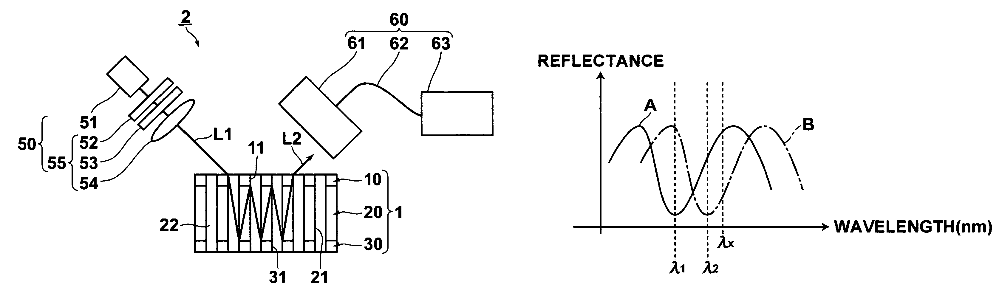
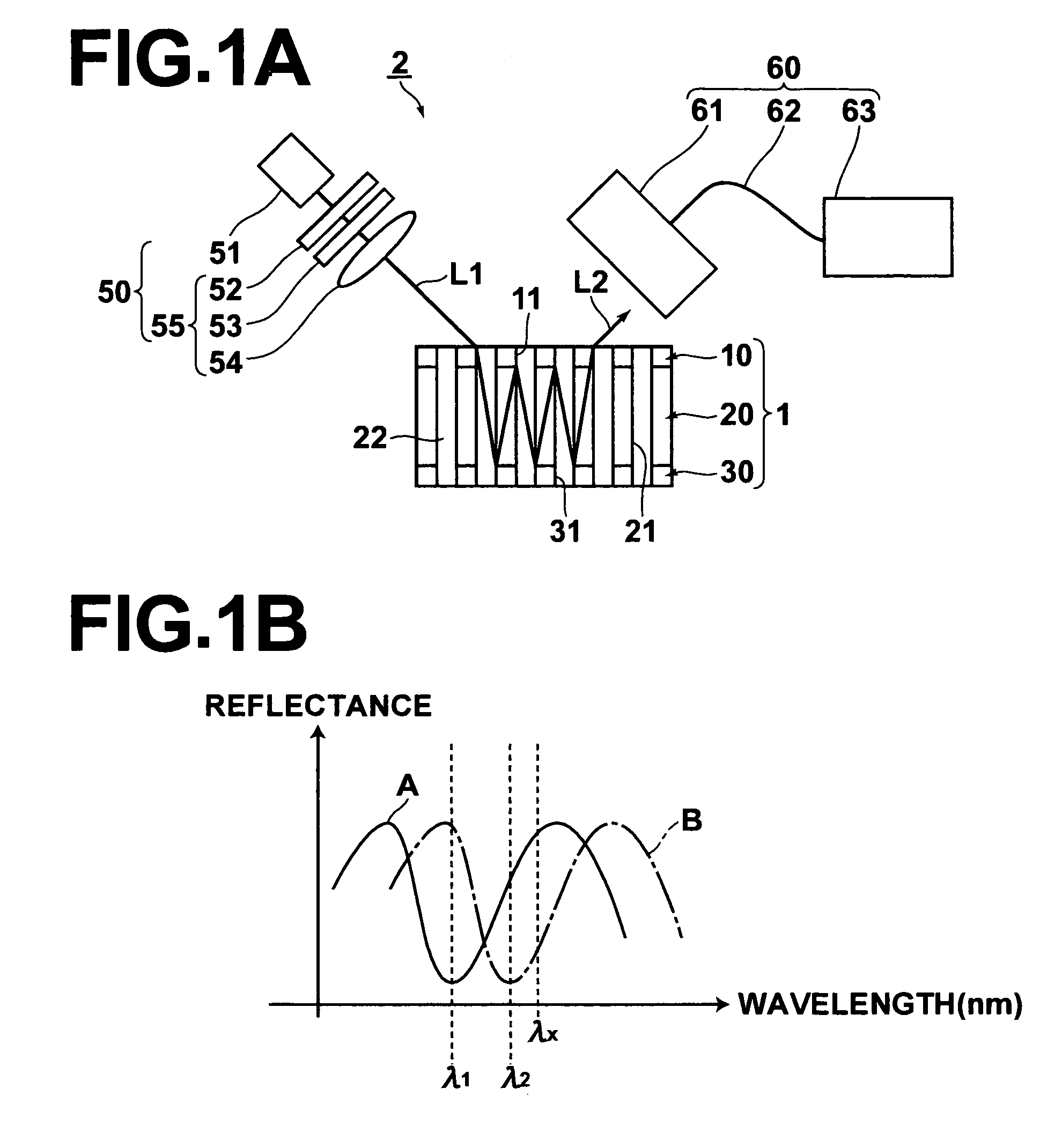
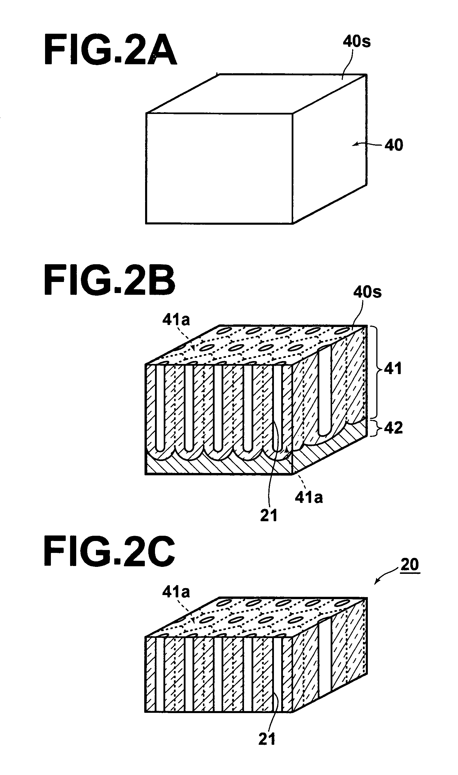
[0051]A fluid analysis element 1 according to a first embodiment of the present invention and a fluid analysis apparatus 2 that employs the fluid analysis element will be described with reference to FIGS. 1A through FIG. 2C. FIG. 1A is a schematic view of the entire fluid analysis apparatus 2 of the first embodiment (the fluid analysis element 1 is illustrated in cross section in the thickness direction thereof, with hatching omitted). FIG. 1B is a graph illustrating examples of spectra of reflected light beams. FIGS. 2A through 2C are perspective views that illustrate the manufacturing steps of the fluid analysis element 1.

[0052]As illustrated in FIG. 1A, the fluid analysis apparatus 2 comprises: the fluid analysis element 1 that emits an emitted light beam L2, which has different physical properties depending on the type of fluid sample 22, when a measuring light beam L1 enters thereinto; a measuring light emitting means 50, for irradiating the measuring light beam L1 onto the flu...

second embodiment

[0095]Next, a fluid analysis element 3 according to a second embodiment of the present invention will be described with reference to FIG. 3. The basic structure of the fluid analysis element 3 is the same as that of the fluid analysis element 1 of the first embodiment. Therefore, common structural elements are denoted with the same reference numerals, and detailed descriptions thereof will be omitted. FIG. 3 corresponds to the illustration of the fluid analysis element 1 of FIG. 1A.

[0096]The fluid analysis element 3 of the second embodiment comprises: a first reflector 10; a transmissive apertured member 20; and a second reflector 30; provided in this order from the side of the element 3 into which the measuring light beam L1 enters, similar to the fluid analysis element 1. However the fluid analysis element 3 differs from the fluid analysis element 1 in that fine apertures 21 of the transmissive apertured member 20 do not penetrate therethrough, and that the second reflector 30 is ...


PUM

PropertyMeasurementUnit
diametersaaaaaaaaaa
temperatureaaaaaaaaaa
applied voltageaaaaaaaaaa

Abstract

A fluid analysis element includes: a semi transmissive / semi reflective first reflector; a transmissive apertured member, having a plurality of apertures, with diameters sufficiently smaller than the wavelength of measuring light, formed therein for holding a fluid sample; and a second reflector, which is fully reflective or semi transmissive / semi reflective. The first reflector, the transmissive apertured member, and the second reflector are provided in this order from the side of the element into which the measuring light enters. Emitted light is emitted from the first reflector or the second reflector. The element displays absorption properties that absorb light of specific wavelengths according to the mean complex refractive indices of the first and second reflectors, and the mean complex refractive index and the thickness of the transmissive apertured member. Analysis of the fluid sample is performed by detecting physical properties or changes in physical properties that occur according to the absorption properties.

Description

BACKGROUND OF THE INVENTION[0001]1. Field of the Invention[0002]The present invention relates to a novel fluid analysis element for analyzing the refractive indices, concentrations, and the like of fluid samples. The present invention also relates to a fluid analysis apparatus.[0003]2. Description of the Related Art[0004]Interference filters, such as etalon filters, are known as light modulating elements that absorb specific wavelengths of light and modulate the light. Conventional interference filters are difficult to manufacture, due to the high requirements regarding accuracy of smoothness and film thickness, and therefore are expensive. In addition, it is difficult to manufacture conventional interference filters having large areas, due to these reasons. Further, because the structures of the conventional interference filters are fixed, the light modulating properties thereof are also fixed. Accordingly, in the case that the wavelength of light to be absorbed (filtered) changes,...

Claims


Application Information

Patent Timeline
Patent Type & Authority Patents(United States)
IPC IPC(8): G01N21/41G01N21/00
CPCG01N21/41G01N21/0303
Inventor TOMARU, YUICHI
Owner FUJIFILM CORP
Why Eureka
Try Eureka