Analyzer

an analyzer and a technology of analyzers, applied in the field of analyzers, can solve the problems of difficult to estimate the traveled distance with high accuracy, and achieve the effect of high accuracy

Active Publication Date: 2012-07-24
KONICA MINOLTA INC
View PDF6 Cites 10 Cited by
  • Summary
  • Abstract
  • Description
  • Claims
  • Application Information

AI Technical Summary

Benefits of technology

[0009]It is an object of the invention to provide an analyzer which can analyze motion of a moving body with high accuracy.
[0011]The analyzer of the present invention is configured to set a plurality of target points in each input image obtained by shooting an image in a surrounding area of the moving body by the image pickup device and calculate the information on at least one of the forward moving speed and the turning speed of the moving body based on the three-dimensional information on the individual target points and the optical flows thereof. Since the analyzer separately calculates the forward moving speed and / or the turning speed of the moving body, the analyzer can analyze the motion of the moving body with high accuracy.

Problems solved by technology

Also, the technique of the aforementioned non-patent document calculates motion parameters without using any three-dimensional information, so that it is difficult to estimate the traveled distance with high accuracy.

Method used


Image

  • Analyzer
  • Analyzer
  • Analyzer

Examples


first embodiment

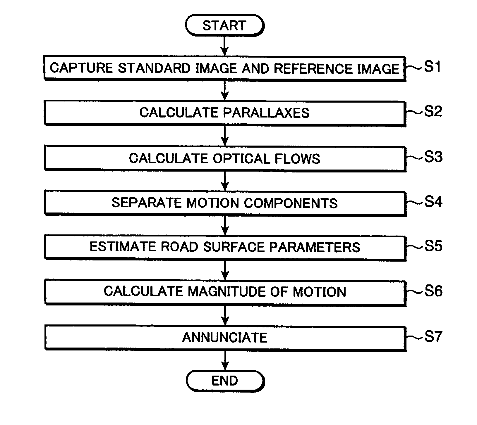
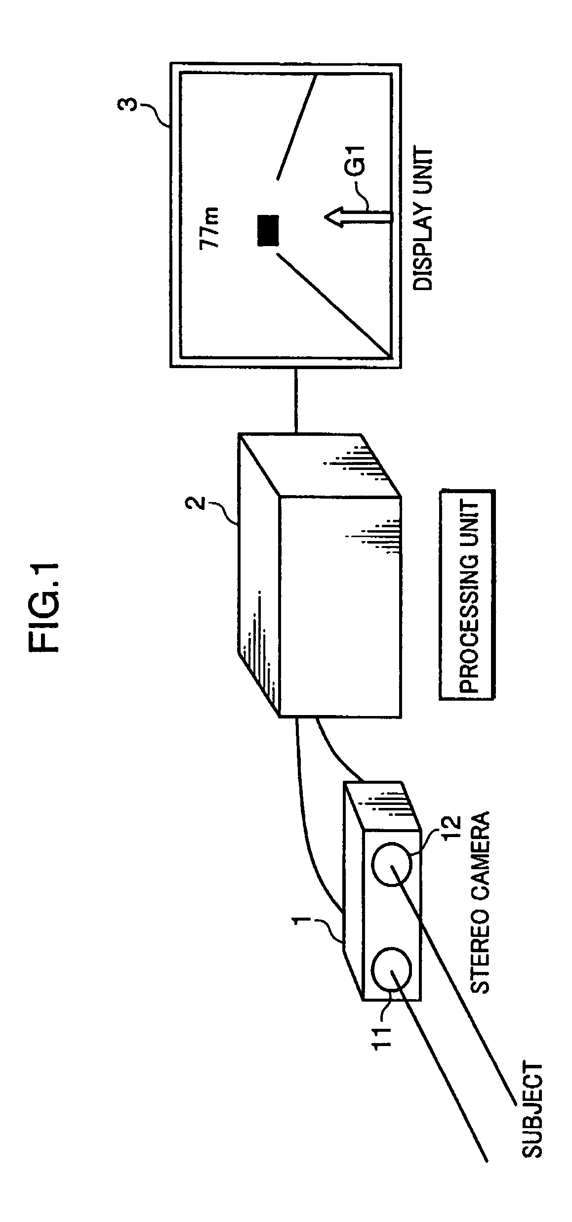
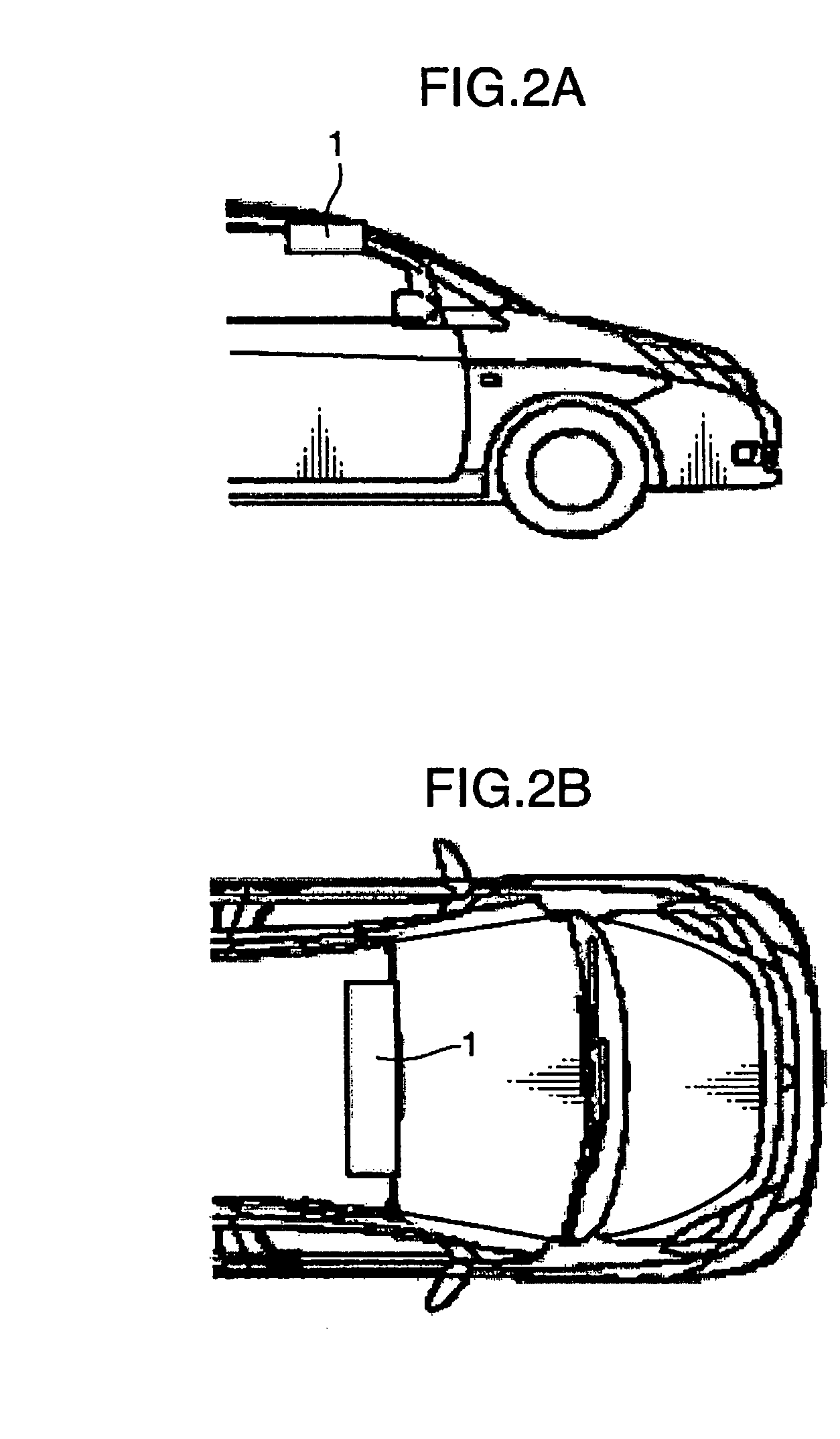
[0036]An analyzer according to a first embodiment of the present invention is now described. FIG. 1 is an overall configuration diagram of the analyzer of the first embodiment of the invention. Installed on a moving body like a motor vehicle, the analyzer is used for analyzing motion of the moving body based on images picked up by a plurality of image pickup devices. As shown in FIG. 1, the analyzer comprises a stereo camera 1, a processing unit 2 and a display unit 3, the stereo camera 1 including a pair of right and left cameras 11, 12 which are examples of the image pickup devices. FIGS. 2A and 2B are diagrams showing an example of a mounting site of the stereo camera 1. In this example, the stereo camera 1 is installed on a roof of the moving body (vehicle) close to a windshield thereof. It is to be noted however that the mounting site of the stereo camera 1 is not limited to the illustrated example but the stereo camera 1 may be installed at any appropriate location as long as ...

second embodiment

[0140]An analyzer according to a second embodiment of the present invention is now described. The analyzer of this embodiment is characterized in that operations performed in steps S4 to S6 differ from the operations performed in the first embodiment. The following discussion of the second embodiment focuses on aspects thereof differing from the first embodiment by omitting the description of common aspects of the two embodiments.

[0141]In this embodiment, the motion component separator 221 shown in FIG. 3 determines straight lines drawn by individual target points assuming that the target points exist on the road surface contained in an input image based on squares of parallaxes and vertical components of optical flows of the individual target points by using the forward moving speed of the moving body and the angular velocity thereof in the pitch direction as variables. The motion component separator 221 then calculates the forward moving speed of the moving body and the angular ve...


PUM


Abstract

A parallax calculator sets a plurality of target points in each standard image and calculates parallaxes of the individual target points. An optical flow calculator calculates two-dimensional optical flows of the individual target points by searching for points corresponding to the target points set in the standard image captured in a frame immediately preceding a current frame. A movement calculation block calculates a forward moving speed of the moving body and angular velocities thereof in both a pitch direction and a pan direction.

Description

[0001]This application is based on Japanese Patent Application No. 2008-021950 filed on Jan. 31, 2008, the contents of which are hereby incorporated by reference.BACKGROUND OF THE INVENTION[0002]1. Field of the Invention[0003]The present invention relates to an analyzer configured to be installed on a moving body (vehicle) for analyzing motion of the moving body.[0004]2. Description of the Related Art[0005]Aiming at preventing traffic accidents, driving support systems using a stereo camera or a radar are actively studied nowadays. A driving support system installed on a vehicle searches for obstacles existing in a moving direction of the vehicle. Upon detecting an obstacle, the system measures the distance to the obstacle, judges whether the obstacle is threatening the vehicle, and if so, produces a warning to a driver or actuates brakes in a controlled fashion. The driving support system also analyzes relative motion of the vehicle and the obstacle. This analysis could provide inf...

Claims


Application Information

Patent Timeline
Patent Type & Authority Patents(United States)
IPC IPC(8): G06K9/00
CPCG06T7/2086G06T2207/10012G06T2207/10021G06T2207/30256G06T2207/30261G06T7/285
Inventor KAWAKAMI, YUICHI
Owner KONICA MINOLTA INC
Why Eureka
Try Eureka