Video centerscope for machine alignment
a technology of video centerscope and machine alignment, which is applied in the field of instruments, can solve the problems of increasing the risk of injury, time-consuming and disruptive work flow, and only working on edges and not on scribed lines
- Summary
- Abstract
- Description
- Claims
- Application Information
AI Technical Summary
Benefits of technology
Problems solved by technology
Method used
Image
Examples
Embodiment Construction
—FIGS. 1-6
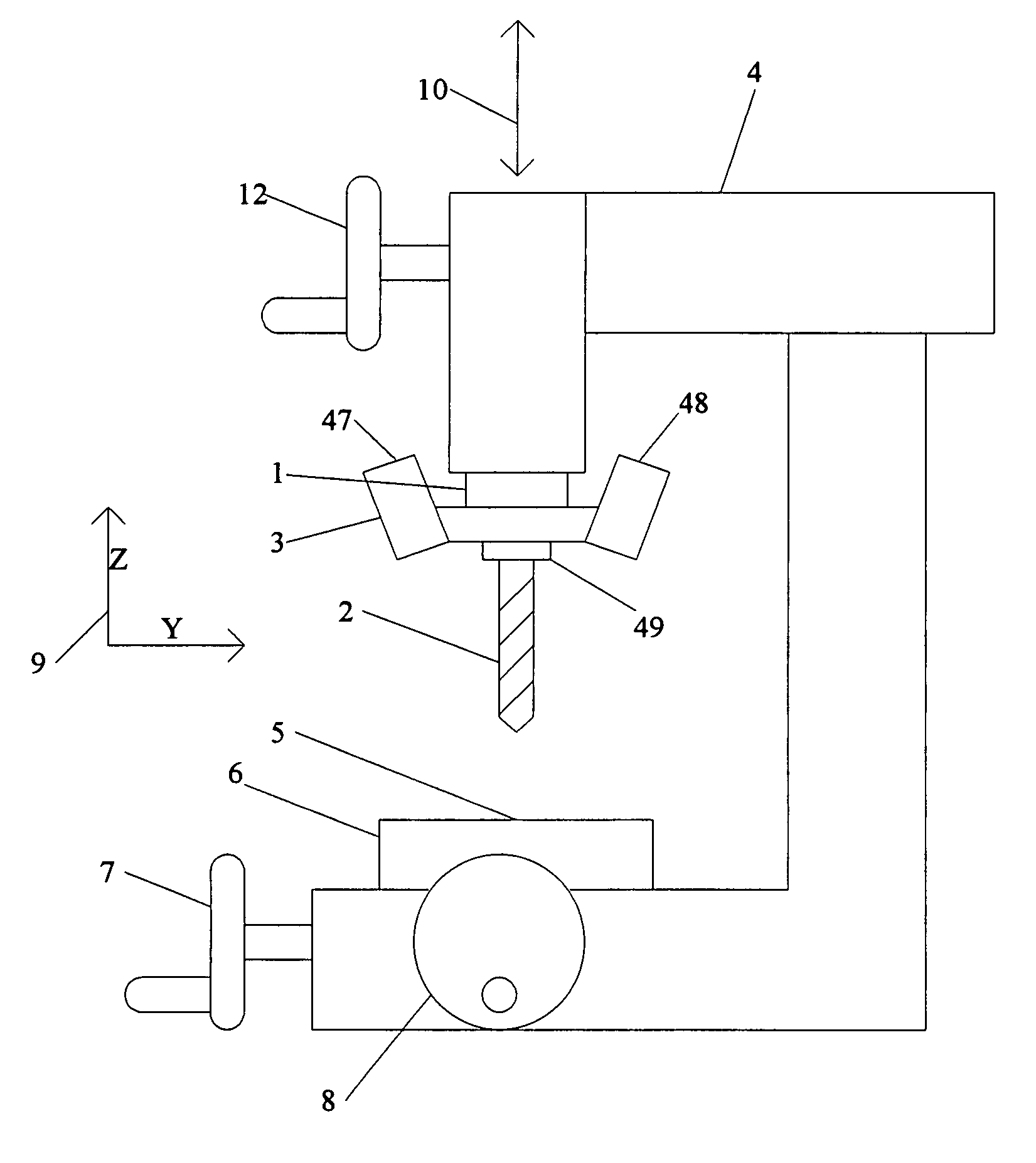
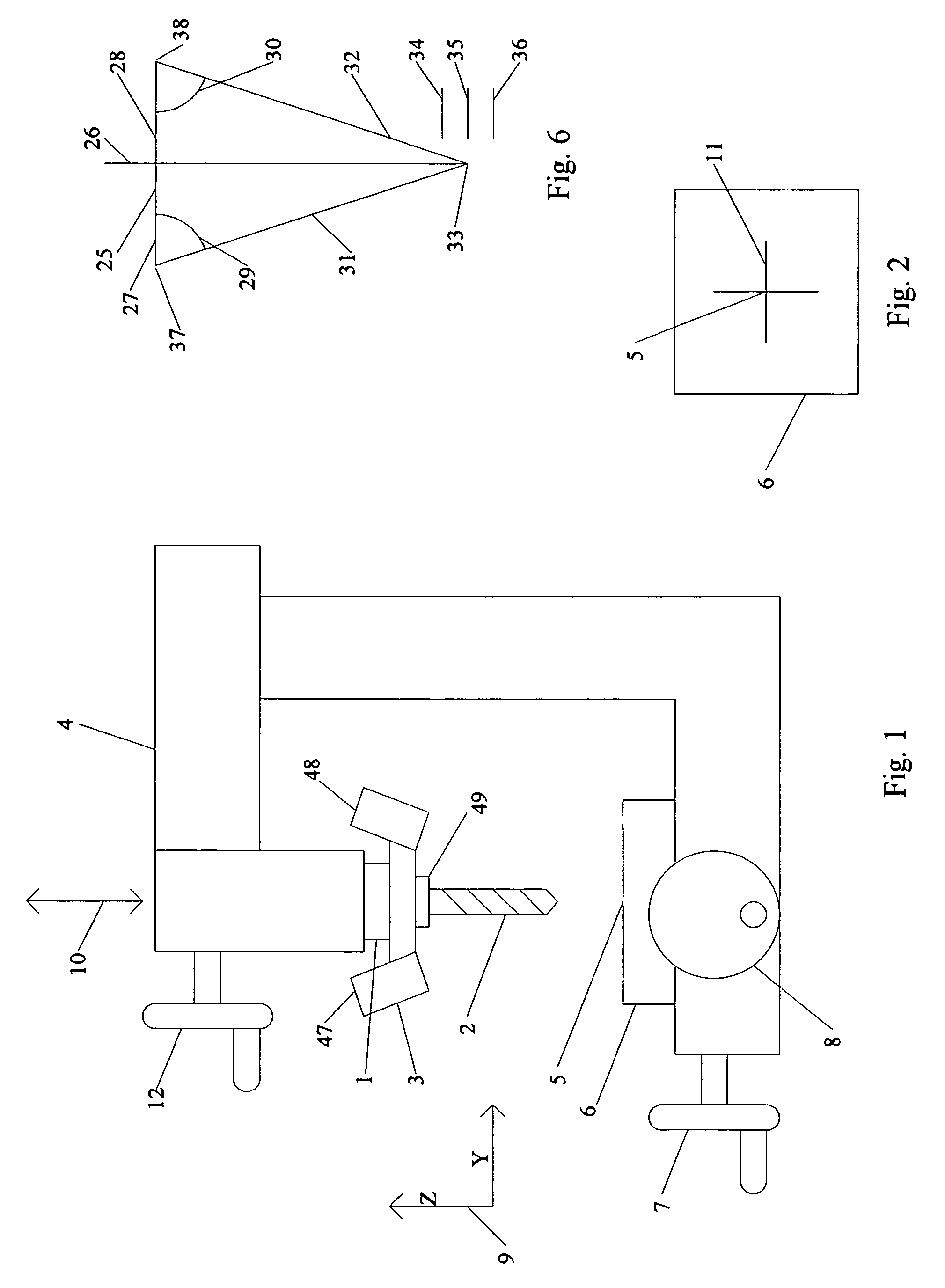
[0081]FIG. 1 shows a typical milling machine 4. The machine has cranks that move the workpiece 6 along two axes. One crank handle 8 moves the workpiece 6 in the X direction. A second crank handle 7 moves the workpiece 6 in the Y direction. A third crank handle 12 moves the quill 1 in the Z direction. There is a graphic 9 that shows the direction of the Y and Z axes. The X axis direction is perpendicular to the drawing.
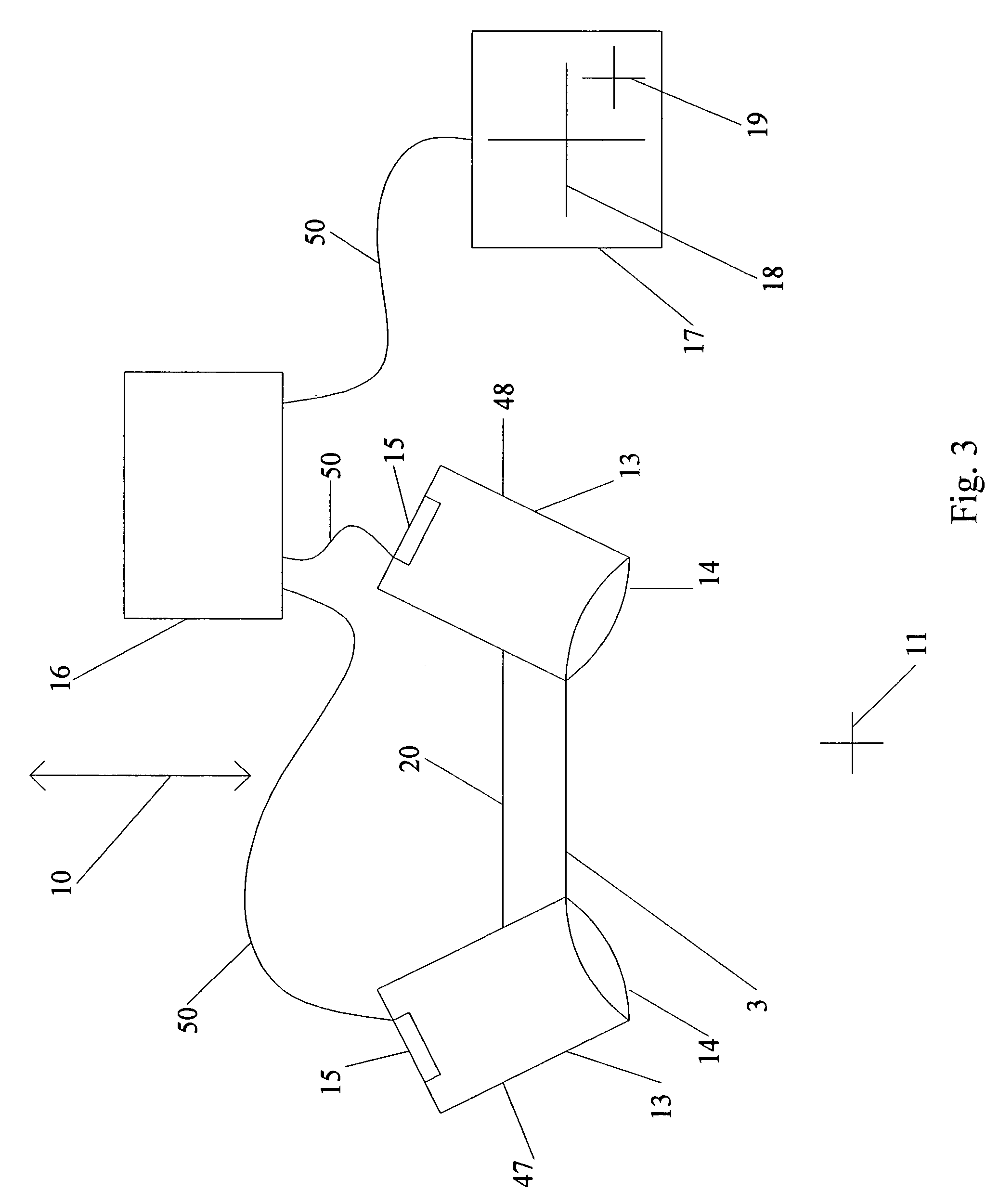
[0082]The quill 1 of the machine 4 holds the spindle 49 to which the cutting tool 2 is attached. The quill 1 is able to move in the Z axis but does not rotate. The quill holds the spindle 49 and the cutting tool 2 both of which do rotate. The center of rotation of the cutting tool is indicated by line 10. The center line 10 indicates the path along which the tip of the cutting tool 2 will travel. If the cutting tool 2 is brought into contact with the workpiece 6 it will touch at the target point 5. In other words the center line 10 is extended would pass thro...
PUM
 Abstract
Description
Claims
Application Information
 - R&D
- Intellectual Property
- Life Sciences
- Materials
- Tech Scout
- Unparalleled Data Quality
- Higher Quality Content
- 60% Fewer Hallucinations
Browse by: Latest US Patents, China's latest patents, Technical Efficacy Thesaurus, Application Domain, Technology Topic, Popular Technical Reports.
© 2025 PatSnap. All rights reserved.Legal|Privacy policy|Modern Slavery Act Transparency Statement|Sitemap|About US| Contact US: help@patsnap.com


