System and method for reducing or eliminating streak artifacts and illumination inhomogeneity in CT imaging

a computed tomography and streak artifact technology, applied in tomography, image enhancement, instruments, etc., can solve the problems of inhomogeneous estimation of tissue density, streak artifacts, starburst artifacts, etc., and achieve the effect of reducing or eliminating streak artifacts

Inactive Publication Date: 2008-07-29
VIRTUALSCOPICS
View PDF16 Cites 7 Cited by
  • Summary
  • Abstract
  • Description
  • Claims
  • Application Information

AI Technical Summary

Benefits of technology

[0007]It is therefore an object of the present invention to reduce or eliminate streak artifacts caused by metal implants or the like.

Problems solved by technology

However, the presence of strongly attenuating objects, such as metal implants or fillings, causes streak artifacts, also called starburst artifacts, in the image.
Another problem encountered in CT is inhomogeneous estimation of tissue density caused by inhomogeneous illumination.
While much investigation has been done into reducing or eliminating those problems, a satisfactory technique has not yet been found.
However, the technique of Hu introduces more computational complexity than is desired, and the Hu approach does not appear to have been widely adopted by the radiology community.

Method used


Image

  • System and method for reducing or eliminating streak artifacts and illumination inhomogeneity in CT imaging
  • System and method for reducing or eliminating streak artifacts and illumination inhomogeneity in CT imaging
  • System and method for reducing or eliminating streak artifacts and illumination inhomogeneity in CT imaging

Examples


Embodiment Construction

[0016]The preferred embodiment of the present invention will now be set forth in detail with reference to the drawings.

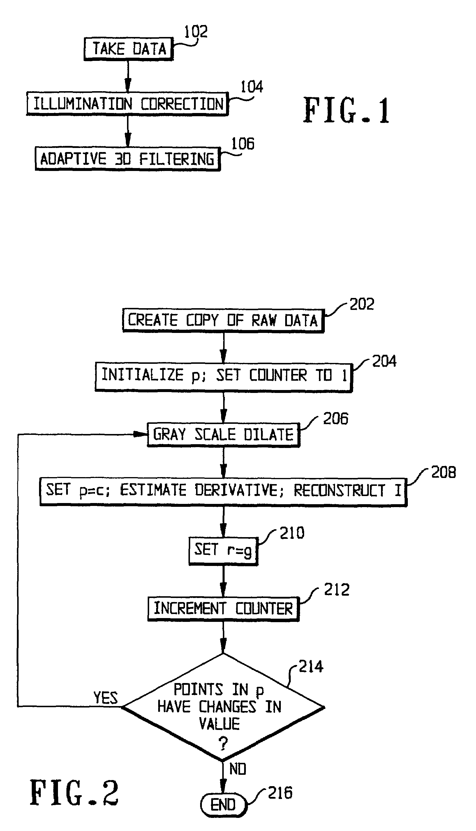
[0017]FIG. 1 shows an overview of the process carried out in the preferred embodiment. After the raw data have been taken in step 102, the process includes two steps: the illumination correction of step 104 and the adaptive 3D filtering of step 106. Those two steps will be explained in detail.

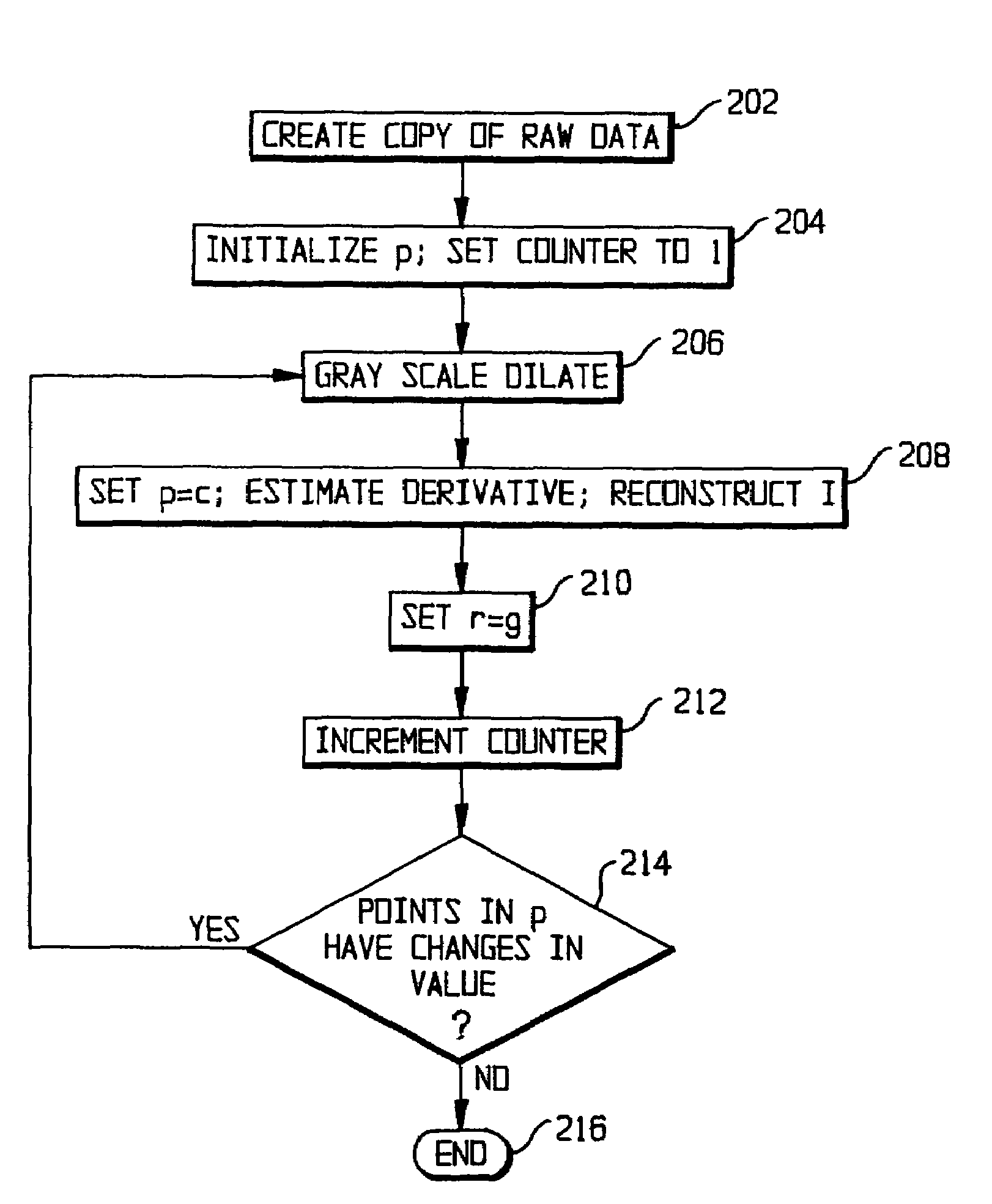
[0018]From a set of reconstructed CT images f(x, y) that contain a metal implant, the algorithm proceeds to stack those images in a three dimensional (3D) volumetric image f(x, y, z). Then, the algorithm gray scale dilates every single slice to estimate a propagation potential field p(x, y, z) of the streak artifacts and to estimate the inhomogeneous illumination I(x, y, z). The estimation of the potential field p(x, y, z) via gray scale dilation is performed through the following steps shown in FIG. 2:

[0019]Step 202. Create a copy of the raw data: r(x, y, z)=f(x, y, z)

[0020]St...


PUM


Abstract

In CT (computed tomography) images, streak artifacts caused by the presence of metal implants and inhomogeneous estimation of tissue density are reduced or eliminated. The algorithm has two basic steps: 1) illumination correction and 2) adaptive 3D filtering. The algorithm starts by estimating the direction of the streak and the degree of inhomogeneous densities by gray scale morphology dilatation. Then, it proceeds to estimate the correct densities based on the estimations and to reduce the streak by an adaptive 3D filtering whose parameters depend on the streak direction and the local image contrast.

Description

REFERENCE TO RELATED APPLICATIONS[0001]The present application is a continuation of U.S. patent application Ser. No. 09 / 908,492, filed Jul. 19, 2001, now U.S. Pat. No. 6,801,646.FIELD OF THE INVENTION [0002]The present invention is directed to a system and method for processing images obtained through computed tomography (CT) or the like and more particularly to such a system and method in which artifacts caused by the presence of metal implants are reduced or eliminated.DESCRIPTION OF RELATED ART [0003]X-ray computed tomography (CT) is an important imaging technique, particularly in medical and dental applications. A series of X-ray beams from many different angles are used to create cross-sectional images of the patient's body. Those images from multiple slices are assembled in a computer into a three-dimensional picture that can display organs, bones, and tissues in great detail. CT offers high spatial resolution, three-dimensional registration and minimal blurring caused by moti...

Claims


Application Information

Patent Timeline
Patent Type & Authority Patents(United States)
IPC IPC(8): G06K9/40G06K9/00A61B6/03G06T1/00G06T5/00
CPCG06T5/002G06T5/009G06T2207/30004G06T2207/10081A61B6/5258
Inventor PENA, JOSE TAMEZTOTTERMAN, SAARA MARJATTA SOFIAPARKER, KEVIN J.
Owner VIRTUALSCOPICS
Why Eureka
Try Eureka