Agricultural article inspection apparatus and method employing spectral manipulation to enhance detection contrast ratio

a technology of spectral manipulation and inspection apparatus, applied in the direction of counting objects on conveyors, investigating moving fluids/granular solids, instruments, etc., can solve the problems of difficult detection of pit fragments, a considerable agricultural processing challenge, and the inability of blades to always adequately secure the pits, etc., to achieve the effect of reducing the reflectance of chlorophyll

Inactive Publication Date: 2002-06-25
KII TEKU INC
View PDF16 Cites 62 Cited by
  • Summary
  • Abstract
  • Description
  • Claims
  • Application Information

AI Technical Summary

Benefits of technology

A sorting 
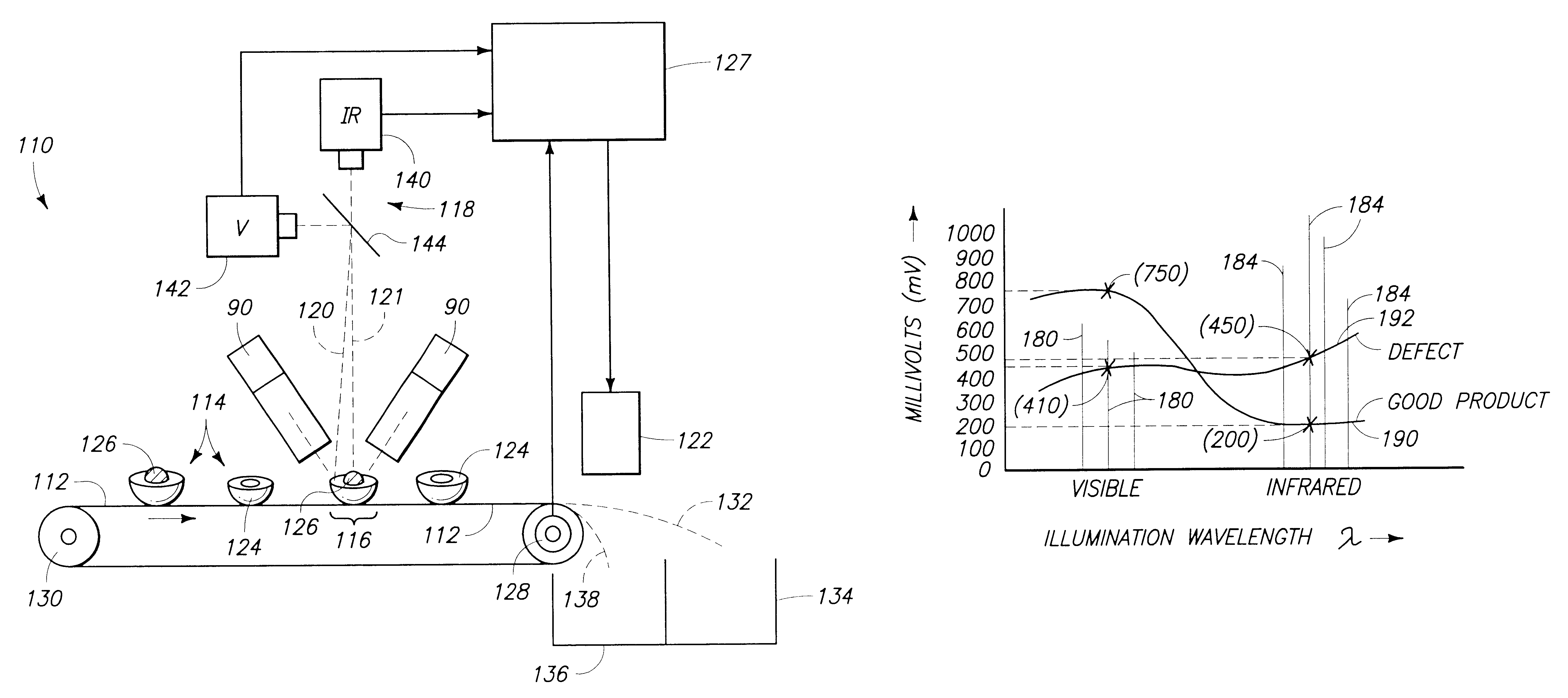
system of this invention conveys agricultural articles, such as peach halves, some of which include pits or pit fragments, on a conveyor belt past an inspection zone that is lighted by an illumination source that radiates both visible and infrared ("IR") radiation. The illumination source generates numerous peaks of visible and IR radiation over a broad spectrum. A preferred illumination source includes a high-pressure Indium Iodide doped high intensity discharge lamp. The radiation is reflected off a parabolic reflector and through a "soda straw" collimator to illuminated the peaches. A detector system employs line scanning visible and IR cameras to sense visible and IR wavelength reflectance value differences existing between the peach meat and the peach pit or pit fragments. Because peach flesh and peach pits exhibit a reversal in the reflectance values between the visible and IR wavelengths, an image analysis technique, such as subtraction or division, is employed to enhance the image contrast. The data subtraction technique also cancels "glint" caused by specular reflections of the illumination off the peaches and into the cameras. In other embodiments of this invention, the visible and infrared image data may be processed using various other image processing methods, such as ratioing, logarithmic, regression, combination, statistical distance, and shape determination to enhance the image detection contrast and classify the resulting data to make sorting decisions.
FIGS. 8 and 9 show plan and elevation views of a preferred illumination source 90 of this invention that provides uniform, intense, parallel illumination of a linear inspection zone. An HID lamp 92, having a length of about 30 cm (12 inches) and filled with a Indium Iodine gas mixture, is positioned at the focus of a cylindrical parabolic reflector 94. HID lamp 92 is oriented so that its longitudinal axis is aligned with a projection axis 96 of reflector 94. Reflector 94 is formed from polished aluminum having a protective dielectric surface coating and may be gold-plated to enhance its IR reflectivity. Illumination source 90 includes mirror-surfaced top and bottom caps 98 that are angled outwardly from lamp 92 and become parallel planar mirror surfaces after emerging from reflector 94. Top and bottom caps 98 may also be gold-plated to enhance their IR reflectivity. Substantially all the light rays propagating from HID lamp 92 are received by reflector 94 and caps 98 and are reflected generally along projection axis 96.
A "soda straw collimator" 100 comprises multiple walls 102 extending perpendicularly between top and bottom caps 98 and aligned parallel to projection axis 96. Walls 102 have diffuse surfaces and their length to pitch ratio allows only light rays that are substantially parallel to projection axis 96 to exit illumination source 90, thereby virtually eliminating any shadowing that would be detrimental to detecting peach pits or pit fragments.
Illumination sources 90 of FIGS. 8 and 9 provide a stripe of illumination in inspection zone 116 having a substantially uniform intensity across the width of conveyor belt 112. The illumination system includes a pair of illumination sources 90 facing inwardly from opposite sides of inspection zone 116 to provide detector system 118 an unobscured view of inspection zone 116 and to reduce detection errors caused by shadowing. The particular type of HID lamp 92 employed will depend on the specific reflection characteristic under analysis as described with reference to FIGS. 6 and 7. However, 
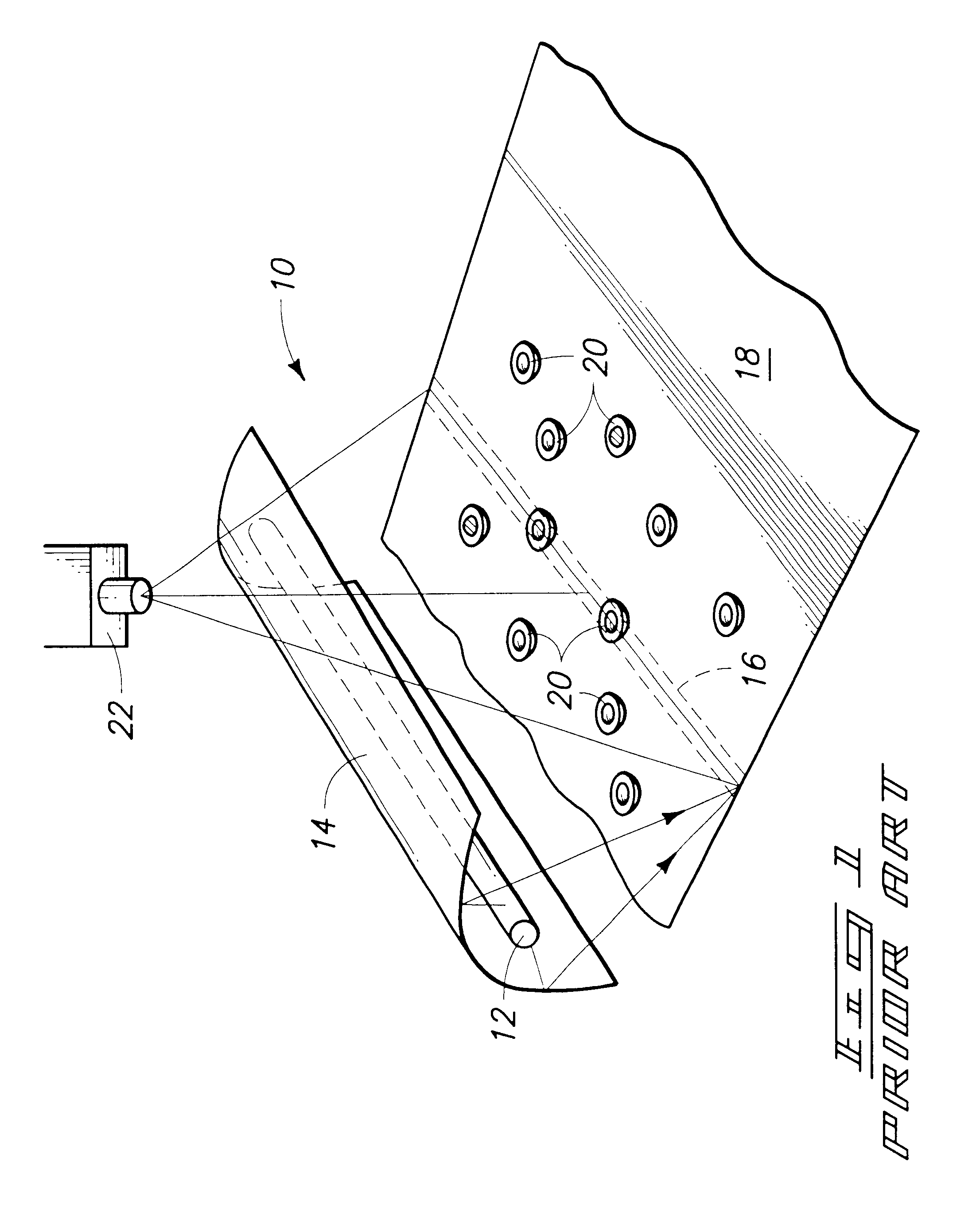
Helium lamps preferably employ the prior art reflector structure shown in FIG. 1.
Subtracting the visible pixel values from the SWIR pixel values yields the following values. For reflected ray 120 (peach meat 124), 520 mV-520 mV=0 mV. Because video levels cannot be negative, any negative values would be set to zero. For reflected ray 121 (peach pits 126), 720 mV-180 mV=540 mV. The net result is that peach meat 124 drops out of the image and only peach pit 126 are detected. This subtraction technique drives the contrast to infinity and makes peach sorting considerably easier. By adjusting the video gain of either the visible or SWIR cameras this effect can be enhanced or diminished.
FIG. 12 is a Polaroid photograph taken of a television monitor displaying a two-dimensionally image generated from the video output of the SWIR camera viewing a peach with an embedded pit. The illumination source includes an Induim Iodide arc discharge lamp. The peach was prepared by splitting it with a knife and immersing it in a warm 12 percent sodium hydroxide solution for 30 seconds. This preparation removes a portion of the peach flesh tendrils attached to the pit and diminishes chlorophyll effect reflectance from the peach meat. The horizontal white line traversing the peach and pit has been superimposed on the television monitor by a Tektronix waveform measurement system to indicate which displayed scan line is being measured by the waveform measurement system. FIG. 12 clearly shows that the pit is substantially brighter that the surrounding peach flesh.

Problems solved by technology

Unfortunately, the blade cannot always adequately secure the pit and when the peach halves fall away, the entire pit may stay embedded in one of the halves.
Successful removal of pits from cling peaches presents a considerable agricultural processing challenge.
Unfortunately, the pit color closely matches the color of peach flesh.
Moreover, the inspectors often have to manually detect small "hidden" pit fragments by wiping the tip of their fingers around the cavity left in the peach by a removed pit.
These inspection difficulties have previously ruled out automatically inspecting peach halves with machine vision techniques that detect visual wavelengths of light because the close color match between peach flesh and pits and the hidden nature of many pit fragments would render such inspection unreliable.
Moreover, this technique is not entirely shadowless, which makes pit fragment detection difficult.
However, this technique is impractical because the illumination intensity decreases inversely with the square of the distance from the light source.
Illumination source 30 simulates multiple illumination point sources propagating from a significant distance, but is not very energy efficient because the illumination from each of lamps 32 is spread over a relatively large area of belt 18.
This is a labor intensive process that is prone to errors.
In illumination source 40, only those light rays that intersect flat back surfaces 46 of projection lenses 44 are focused on inspection zone 16 of conveyor belt 18, which renders this technique inefficient.

Method used


Image

  • Agricultural article inspection apparatus and method employing spectral manipulation to enhance detection contrast ratio
  • Agricultural article inspection apparatus and method employing spectral manipulation to enhance detection contrast ratio
  • Agricultural article inspection apparatus and method employing spectral manipulation to enhance detection contrast ratio

Examples


Embodiment Construction

In the foregoing experimental results, subtraction can be used to increase the detection contrast because the pit reflectivity is higher than the meat reflectivity in the SWIR wavelengths and lower in the visible wavelengths. Subtraction is not the only image processing technique useful for increasing the detection contrast. For example, image processing employing division (ratio) may improve image contrast for certain illumination and product combinations.

FIGS. 18 and 19, show simplified reflectance versus illumination wavelength graphs for peaches and a generic agricultural product. In particular, illumination is shown by spectral lines representing visible wavelengths 180, SWIR wavelengths 182, and IR wavelengths 184.

In particular, FIG. 18 shows curves representing detected reflectance versus illumination wavelength for peach meat 186 and a peach pit 188. Detected reflectance is shown as milliVolts of detected signal, with peach meat 186 producing a 300 mV signal at visible wavel...


PUM

PropertyMeasurementUnit
lengthaaaaaaaaaa
IR wavelengthsaaaaaaaaaa
visible wavelengthsaaaaaaaaaa

Abstract

A sorting system (110) conveys articles, such as peaches (114) on a conveyor belt (112) past an inspection zone (126) that is lighted by an illumination source (90) radiating a number of emission peaks over visible and infrared portions of the spectrum. The illumination source generates the radiation from an Indium Iodide lamp (92) that is reflected off a parabolic reflector (94) and through a "soda straw" collimator (100) to illuminated the peaches. A detector system (118) employs line scanning visible and infrared cameras (142, 140) to sense visible and IR wavelength reflectance values for the peach meat (124) and peach pit or pit fragments (126). Various image processing and analysis methologies, such as subtraction, ratio, logarithmic, regression, combination, angle, distance, and shape may be employed to enhance the image contrast and classify the resulting data for sorting the peaches. Employing subtraction also cancels "glint" caused by specular reflections of the illumination source off the peaches and into the cameras.

Description

This invention relates to agricultural product inspection and more particularly to an apparatus and a method of inspecting peach halves for pits and pit fragments.A popular agricultural product is canned peach halves, slices and cubes. The peach variety typically used for canning is referred to as a "cling" peach, whereas the popular eating peach variety is referred to as "the free stone" peach, which is not used for canning because they lose their taste during the canning process. The variety names cling and free stone imply the relative ease with which the stone (hereafter "pit") can be removed from the fruit.Many peach processors employ an Atlas splitting machine to remove the pit. This machine consist of a circumferential knife, that looks and functions much like the iris of a camera lens. As the blades of the machine close down on the peach, it cuts through the flesh until it meets the hard core of the pit. Once the pit is secured firmly in place by means of the blade, two cups...

Claims


Application Information

Patent Timeline
Patent Type & Authority Patents(United States)
IPC IPC(8): B07C5/342G01N21/31
CPCB07C5/3422G01N21/31G01N21/85G01N2021/8466Y10S209/938
Inventor CAMPBELL, DUNCAN B.EWAN, JAMESLEIDECKER, CLIFF J.SQUYRES, H. PARKSKALAYEH, HOOSHMAND M.
Owner KII TEKU INC
Why Eureka
Try Eureka