Method and system for imaging an object or pattern

a technology of object and pattern, applied in the field of method and system for imaging an object or pattern, can solve the problems of increasing capture time, affecting the effect of image quality, and difficult to obtain the proper illumination,

Inactive Publication Date: 2003-08-05
RUDOLPH TECHNOLOGIES INC
View PDF67 Cites 62 Cited by
  • Summary
  • Abstract
  • Description
  • Claims
  • Application Information

AI Technical Summary

Problems solved by technology

Obtaining the proper illumination is particularly difficult when working with specular (mirror-like) surfaces, especially when the specular surfaces are curved or multifaceted.
However, good contrast sometimes requires edges to be highlighted which is best obtained from collimated unidirectional light, not uniformly diffuse light.
Unfortunately, the sequential illumination method increases capture time since a separate picture is required for each illumination--each video picture typically requires 1/30 second.
Furthermore, the combined image tends to look smeared if th...

Method used


Image

  • Method and system for imaging an object or pattern
  • Method and system for imaging an object or pattern
  • Method and system for imaging an object or pattern

Examples


Embodiment Construction

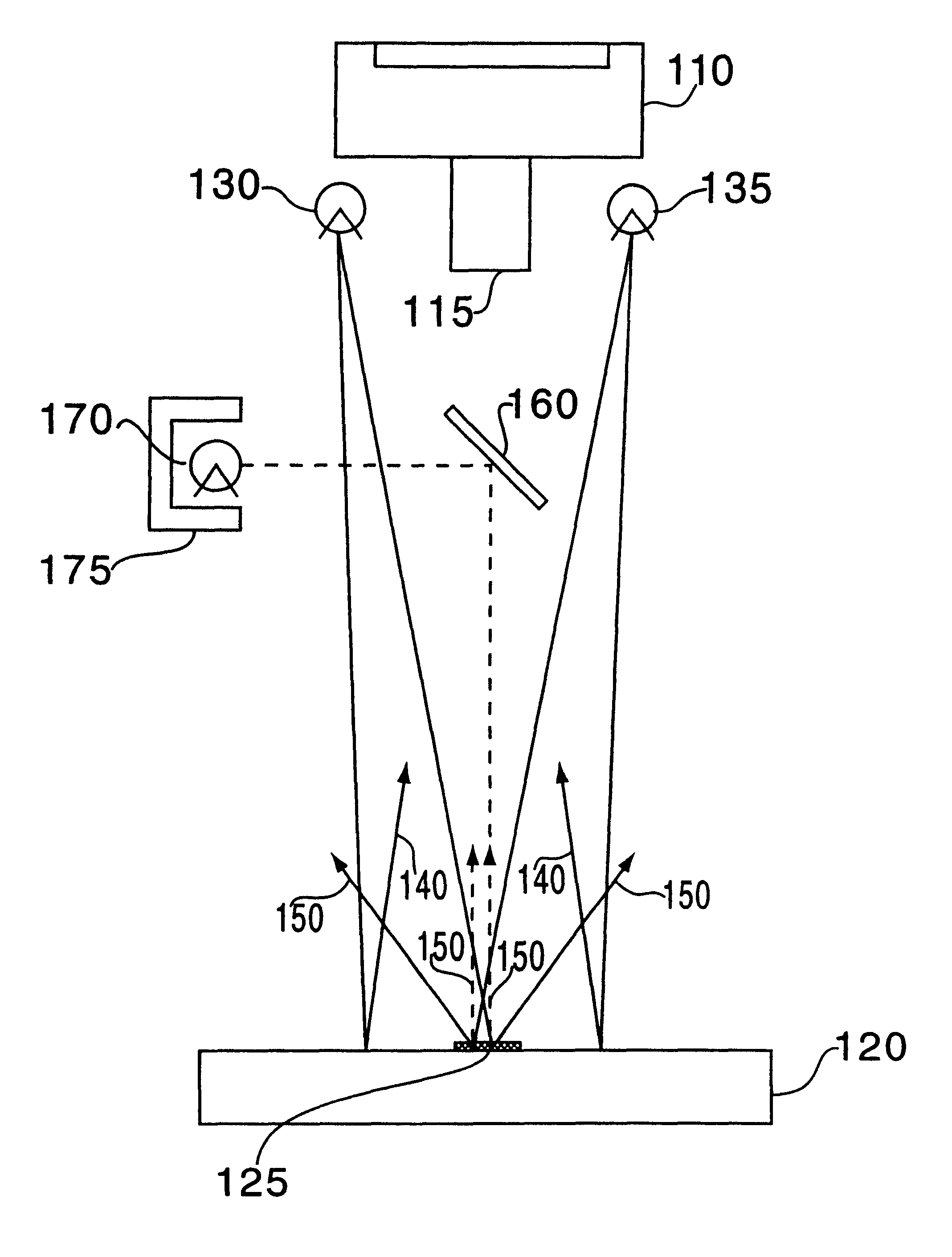
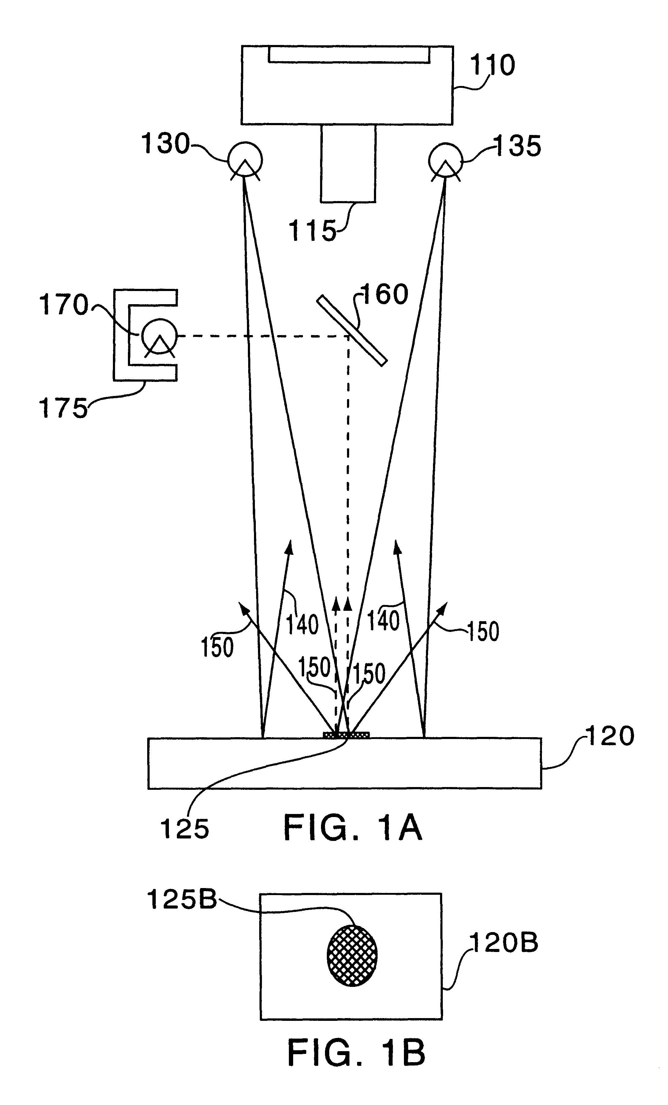
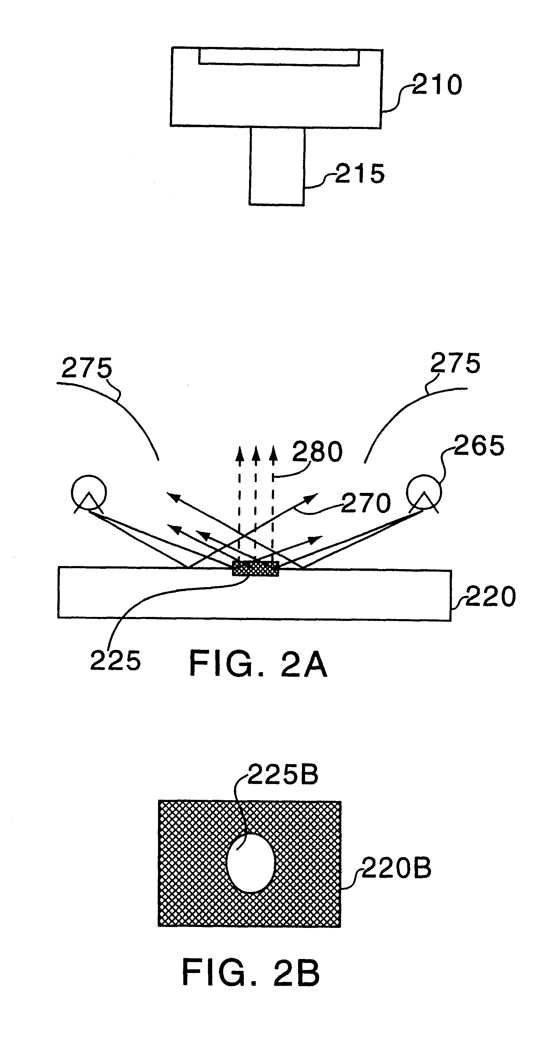
When imaging characters (e.g., serial numbers) that are positioned on a semiconductor wafer, prior art systems typically require that light sources be located at a particular critical location according to the reflectance properties of both the wafer and the characters on the wafer. However, both surface and sub-surface properties may change depending on where in the semiconductor manufacturing process (i.e., what process step) the characters are being imaged. With prior art systems, many illumination locations may have to be tested before the characters can be properly read. An example of various type of illumination that could be used for imaging characters on a wafer using standard machine vision techniques is shown in FIG. 4C. As illustrated, characters on wafer 400C are sequentially illuminated by a high dark field light source 410C, (used to produce a dark-field image), a high DOAL (diffuse on axis light) 420C (positioned to produce a bright-field image), and a low DOAL 430C (...


PUM


Abstract

A system and method for simultaneously obtaining a plurality of images of an object or pattern from a plurality of different viewpoints is provided. In an exemplary embodiment, proper image contrast is obtained by replacing the light sources of earlier systems with equivalent light sensitive devices and replacing the cameras of earlier systems with equivalent light sources. With such a system, bright-field images and dark-field images may be simultaneously obtained. In one aspect of the invention, a light source is positioned to illuminate at least a portion of an object. A plurality of light guides having input ends are positioned to simultaneously receive light reflected from the object and transmit the received light to a plurality of photodetectors. The light guides are arranged such that their respective input ends are spaced substantially equally along at least a portion of a surface of an imaginary hemisphere surrounding the object. The signals generated by the photodetectors (as a result of light detection) are processed and a plurality of images of the object are formed. Another aspect of the invention provides a method for generating composite images from simultaneously obtained images. Equivalent regions of each image (corresponding to geographically identical subpictures) are compared. The subpicture having the highest entropy is selected and stored. This process continues until all subpictures have been considered. A new composite picture is generated by pasting together the selected subpictures. In another aspect of the invention, the vector of relative light values gathered for each pixel or region of an object illuminated or scanned (i.e., one value for each photodetector) is used to determine reflectance properties of points or regions illuminated on the object or pattern. The reflectance properties may be stored in a matrix and the matrix used to read, for example, a Bar Code of a data matrix symbol.

Description

The present invention is directed to a system and method for imaging objects or patterns. More particularly, the present invention is directed to a system and method for simultaneously obtaining a plurality of images of an object or pattern from a plurality of different viewpoints.COPYRIGHT NOTICEA portion of the disclosure of this patent document contains material which is subject to copyright protection. The copyright owner has no objection to the facsimile reproduction by anyone of the patent document or patent disclosure as it appears in the Patent and Trademark Office, patent file or records, but otherwise reserves all copyright rights whatsoever.BACKGROUND IN THE INVENTIONMachine vision systems are commonly used in industry for high speed inspections. In particular, these systems are used to obtain digital images of objects in order to determine, with a computer, whether the object is of "acceptable" quality with respect to predetermined specifications. For example, a system m...

Claims


Application Information

Patent Timeline
IPC IPC(8): G06T1/00G06T7/00G06T5/50
CPCG01N21/8806G06T1/00G06T1/0007G06T5/50G06T7/0002G06T7/0004G01N21/9501G01N21/95607G01N2021/8825G01N2021/95646G02B21/367G06T2200/32G06T2207/30148G06T2207/30152
Inventor STERN, HOWARDMAALI, FEREYDOUN
Owner RUDOLPH TECHNOLOGIES INC
Why Eureka
Try Eureka