Ice-making machine

a technology of ice-making machines and ice-making blocks, which is applied in the field of ice-making machines, can solve the problems of limited amount of ice-making blocks in the refrigerator, inability to make ice-making blocks, and large use trouble, and achieve the effect of quick and regular size of ice-making blocks

Inactive Publication Date: 2008-08-05
TANG YI LIN
View PDF11 Cites 28 Cited by
  • Summary
  • Abstract
  • Description
  • Claims
  • Application Information

AI Technical Summary

Benefits of technology

[0007]The objective of the invention is to offer an ice-making machine able to quickly make ice blocks regular in size.

Problems solved by technology

In addition, it needs to take about an hour to make ice blocks in a conventional family refrigerator and the amount of the ice blocks made in the refrigerator is limited, unable to make ice blocks to meet urgent needs.
Additionally, if there is not any ice-making box for making ice blocks in a conventional family refrigerator, other kinds of containers have to be used instead, but the ice blocks made by these containers are different in size and difficult to be separated from the containers, resulting in much trouble in use.

Method used


Image

  • Ice-making machine
  • Ice-making machine
  • Ice-making machine

Examples


Embodiment Construction

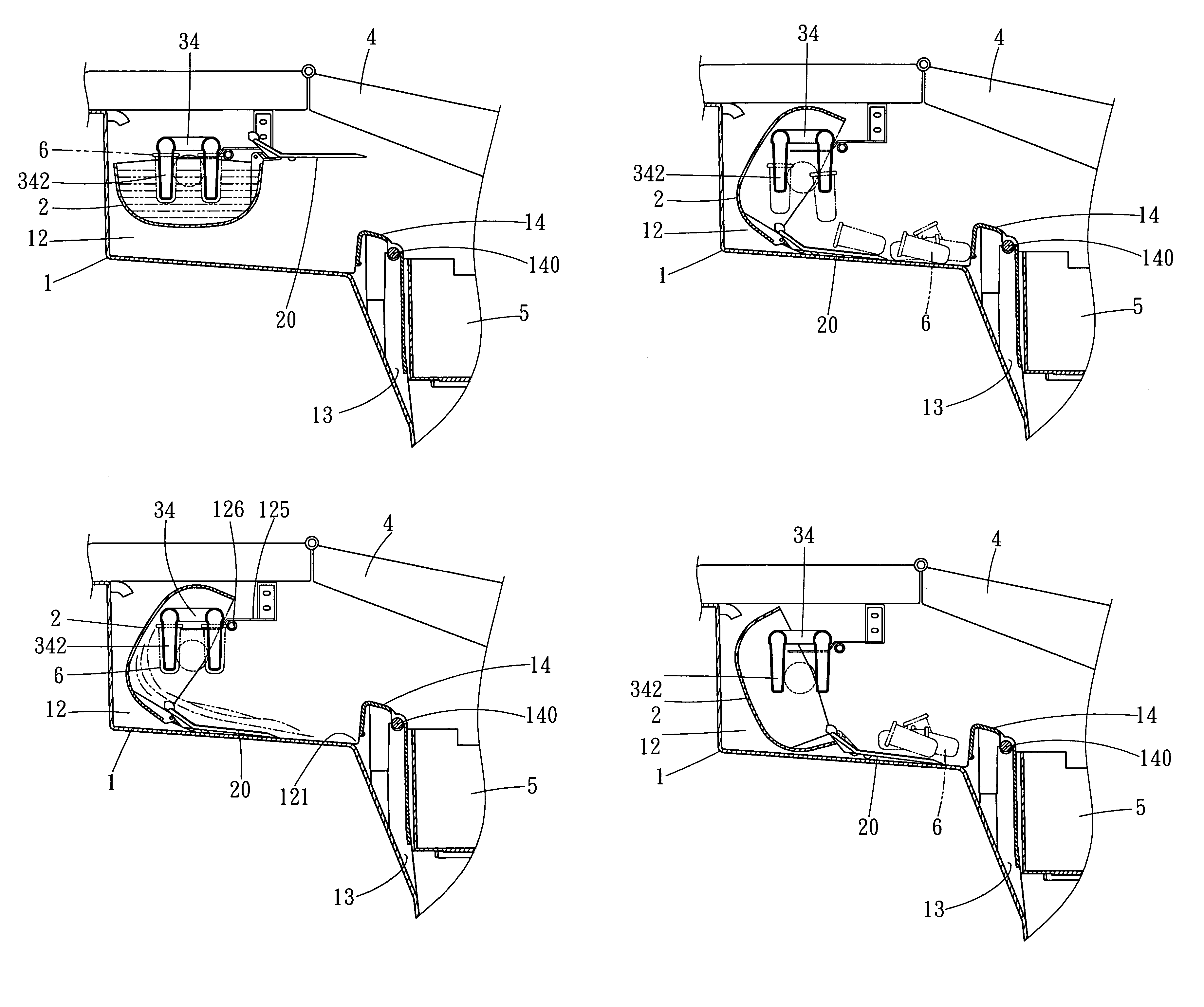
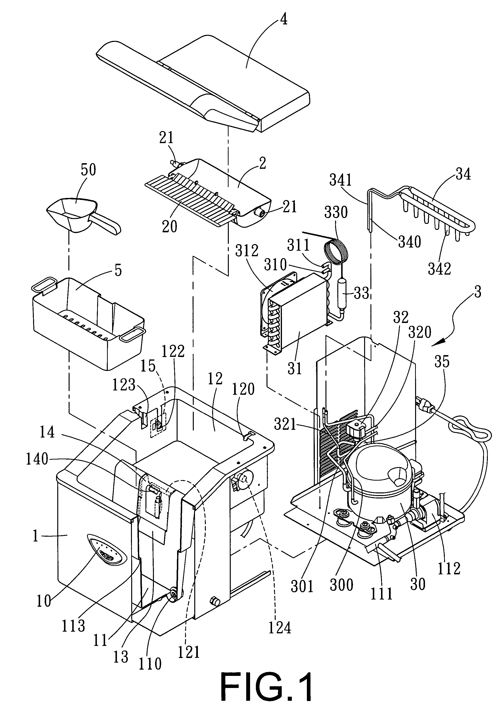
[0023]A preferred embodiment of an ice-making machine in the present invention, as shown in FIGS. 1-5, includes a machine body 1, a water trough 2, a freezing system 3, a filtering cover 4 and an ice box 5 combined together.

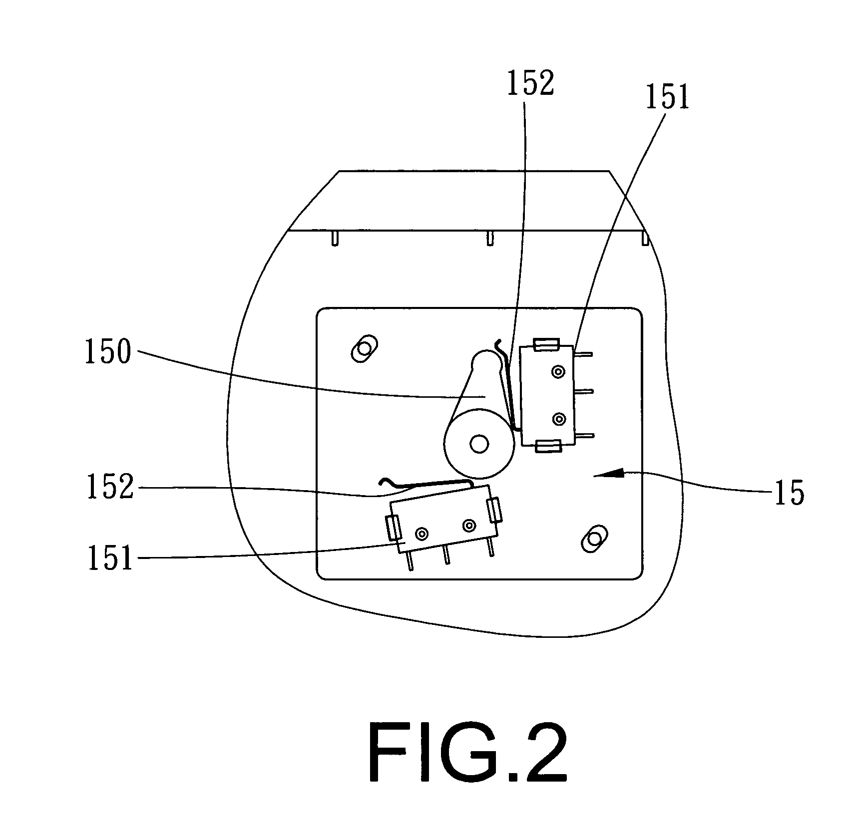
[0024]The machine boy 1 is provided with a control faceplate 10 on a front side and formed with a water tank 11 and an accommodating hollow 12 respectively in the front interior and in the rear upper interior. The water tank 11 has its bottom bored with a water intake 110 having its rear end connected with a water pipe 111 and a pump 112. Further, the water tank 11 is provided with a support edge 113 and the accommodating hollow 12 has one upper end provided with a feed water pipe 120 connected with the water pipe 111. A draining channel 13 is formed between the accommodating hollow 12 and the water tank 11 and has its upper side assembled with a cover 14 having a sensor 140 installed therein, with a draining port 121 formed between the cover 14 and the accommoda...


PUM


Abstract

An ice-making machine includes a control faceplate and formed with a water tank and an accommodating hollow. The water tank has a water intake connected with the feed water pipe of the accommodating hollow. The accommodating hollow is bored with a draining channel communicating with the water tank and has an insert hole in a side and a trigger switch on an outer side. A water trough pivotally assembled in the accommodating hollow has a push plate at the front side and a pivot at the opposite sides to be fitted with the trigger switch. A freezing system installed in the machine body is composed of a compressor, a condenser, an electric magnetic valve, a dryer with a capillary tube, a vaporizer with plural ice-making rods and a liquid reservoir. The water tank has an ice-collecting box.

Description

BACKGROUND OF THE INVENTION[0001]1. Field of the Invention[0002]This invention relates to an ice-making machine, particularly to one provided with a control faceplate on the surface of a machine body that has its interior formed with a water tank and an accommodating hollow. The water tank is bored with a water intake connected to the feed water pipe of the accommodating hollow by a water pipe. The accommodating hollow has its front side bored with a draining channel communicating with the water tank and one side bored with an insert hole and its outer wall provided with a trigger switch. Further, the accommodating hollow has its interior pivotally disposed with a water trough having its front side assembled with a push plate and its opposite sides respectively fixed with a pivot one of which is inserted through the insert hole of the accommodating hollow and fitted with the trigger switch. Furthermore, the machine body has its interior disposed with a freezing system composed of a ...

Claims


Application Information

Patent Timeline
Patent Type & Authority Patents(United States)
IPC IPC(8): F25C1/12
CPCF25C1/08F25C2305/022F25C2700/12F25C2400/14F25C2700/02F25C2400/04
Inventor WANG, CHING-HSIANG
Owner TANG YI LIN
Why Eureka
Try Eureka