Cable gland

a cable gland and cable technology, applied in the field of cable glands, can solve the problems of difficult detection of assembly faults and affect the tightness of the cable gland, and achieve the effect of reliable sealing action and simple assembly

Active Publication Date: 2008-08-05
OPTOSYS SA
View PDF8 Cites 14 Cited by
  • Summary
  • Abstract
  • Description
  • Claims
  • Application Information

AI Technical Summary

Benefits of technology

[0007]It is an object of the invention to avoid this disadvantage and to provide a cab

Problems solved by technology

In a mounted cable gland, it is not visible whether this is the case or not, such that assembly faults are difficult to detect.
Furthermore

Method used


Image

  • Cable gland
  • Cable gland
  • Cable gland

Examples


Embodiment Construction

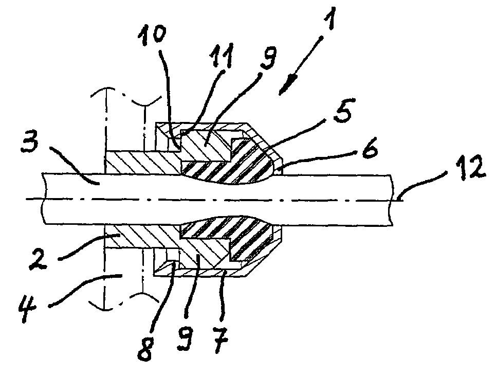
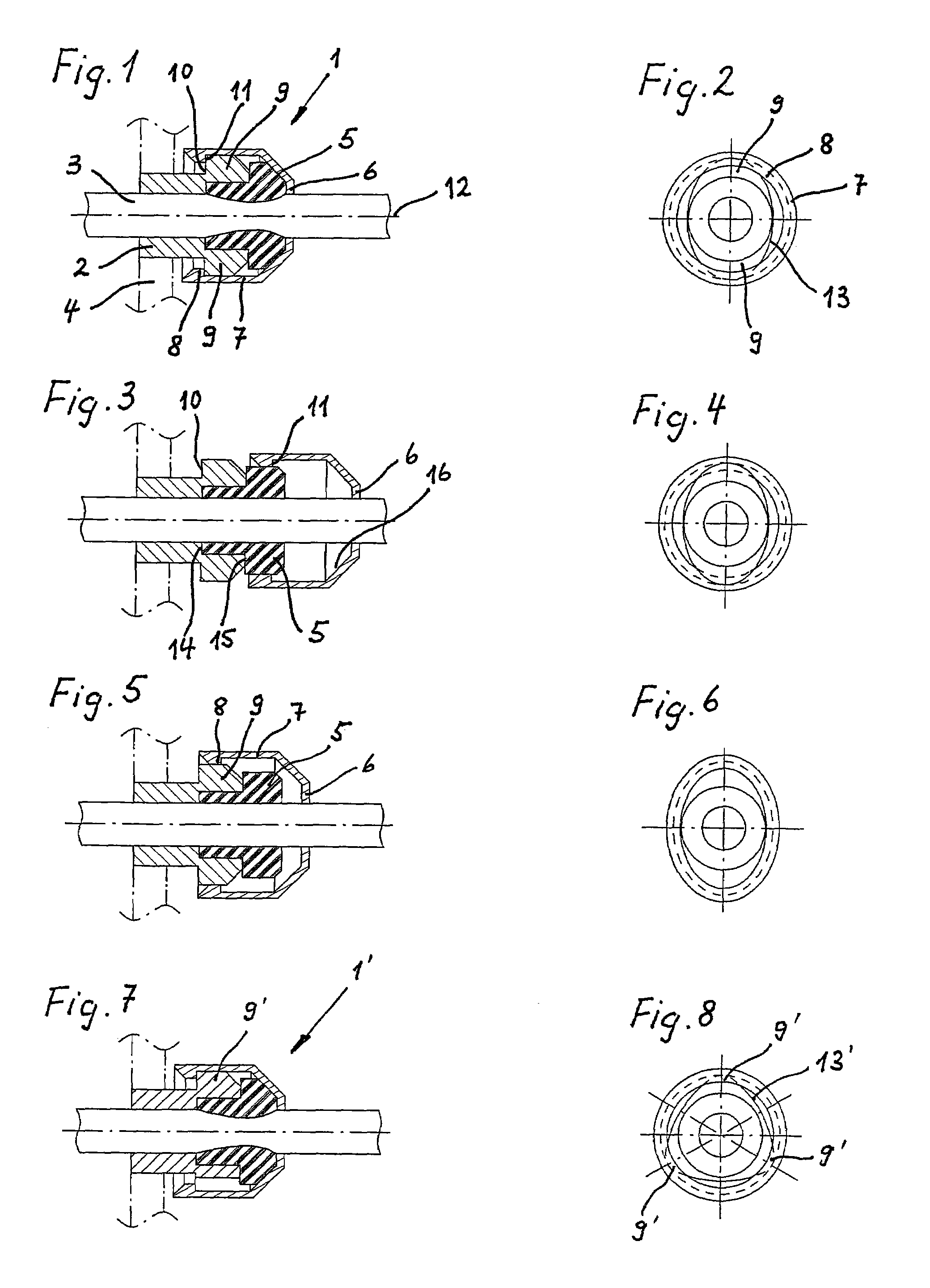
[0016]FIGS. 1 and 2 schematically show a cable gland 1 in its mounted condition. It includes a gland body 2 through the bore of which a cable 3 having a circular cross-section is guided. Gland body 2 is inserted in a wall 4 that is symbolically indicated by chain dotted lines such that the bore of gland body 2 and thus also cable 3 pass through wall 4. Alternatively, gland body 2 might be integrally connected to wall 4.

[0017]To ensure a tight seal of cable 3 in gland body 2, cable gland 1 furthermore includes an elastic sealing ring 5 whose internal diameter essentially corresponds to the diameter of cable 3 and whose front side abuts to gland body 2 in this assembled condition, as well as a gland ring 6 that abuts to the sealing ring opposite to the gland body and is maintained by connecting means at such an axial distance from the gland body that the sealing ring is clamped between the gland ring and the gland body. The radially inner surface of the sealing ring is thereby pressed...


PUM


Abstract

The invention relates to a cable gland. The latter comprises a gland body for feeding a cable therethrough, an elastic sealing ring that is applicable to the front side of the gland body and whose internal diameter essentially corresponds to the diameter of the cable, and a gland ring that is applicable to the sealing ring on the opposite side of the gland body and is maintained by connecting means in an assembled condition at such an axial distance from the gland body that the sealing ring is clamped between the gland ring and the gland body so that its radially inner surface is pressed against the cable. These connecting means form a snap-on connection that is closable for the assembly of the cable gland by axially pushing together the gland ring and the gland body and that connects the gland ring and the gland body undetachably in their closed condition. A preferred field of application are encapsulated sensors having an enclosure into which a connecting cable is guided through a gland body of a cable gland that passes through the enclosure wall.

Description

CROSS REFERENCE TO RELATED APPLICATIONS[0001]This application claims the benefit of the filing date of European Patent Application No. 05405514.0 filed 1 Sep. 2005, the disclosure of which is hereby incorporated by reference.BACKGROUND OF THE INVENTION[0002]1. Field of the Invention[0003]The invention relates to a cable gland, and to an encapsulated sensor provided with the cable gland.[0004]2. Description to the Related Art[0005]For a tight feedthrough of a cable trough a wall, it is known in the art to guide the cable through a gland body and to clamp a sealing ring between the gland body and a coaxially arranged gland ring such that its radially inner surface is pressed against the cable. In the cable gland disclosed in Swiss Patent Specification CH480747, the gland ring is formed by the bottom portion of a coupling nut that is screwed onto the gland body, and the sealing ring is compressed by tightening the coupling nut.[0006]In cable glands of this kind, a tight seal is only en...

Claims


Application Information

Patent Timeline
IPC IPC(8): H02G3/06
CPCH02G3/0658Y10T16/05H02G3/22H01R13/52
Inventor HEIMLICHER, PETERCHARRIERE, FABRICE
Owner OPTOSYS SA
Why Eureka
Try Eureka