Method and apparatus for coupling laser beams

a laser beam and laser beam technology, applied in lasers, laser details, instruments, etc., can solve the problems of inability to use temporal interleaving, limited to combining only two beams, and not practicable for combining unpolarized beams

Active Publication Date: 2008-08-05
COHERENT GMBH
View PDF11 Cites 21 Cited by
  • Summary
  • Abstract
  • Description
  • Claims
  • Application Information

AI Technical Summary

Problems solved by technology

Temporal interleaving cannot be used when it is desired to combine beams either for increasing CW power or for increasing peak power in a pulse or a repeated sequence of pulses.
This method however, is practically limited to combining only two beams, and is not practical for combining unpolarized beams.
This method is only useful however in applications that are insensitive to the bandwidth of radiation.
It has been determined that in the above-described beam coupling apparatus the homogenization of the beams prior to coupling is insufficient in itself to provide uniform, temporally-constant illumination in image plane 40.
However, if, for example, the powers of the beams leaving the two homogenizers 20A and 20B differ, or in the case of interleaving laser operation, the illumination cones for each image point will show an asymmetric angular power distribution, and the telecentricity of the image projection is impaired, giving rise to variations of the image power distribution (shot-to-shot variations) under practical operation conditions.
Unfortunately, in high-power lasers of any kind, this is rarely the case.
In excimer laser beams, where pulses may have a duration as short as about 20 nanoseconds (ns) or less, an exact or consistent temporal overlap is very difficult to achieve.
Clearly, while the above-discussed problems are discussed in the context of one particular method of beam coupling at least one of the problems would be encountered in other beam coupling methods.

Method used


Image

  • Method and apparatus for coupling laser beams
  • Method and apparatus for coupling laser beams
  • Method and apparatus for coupling laser beams

Examples


Embodiment Construction

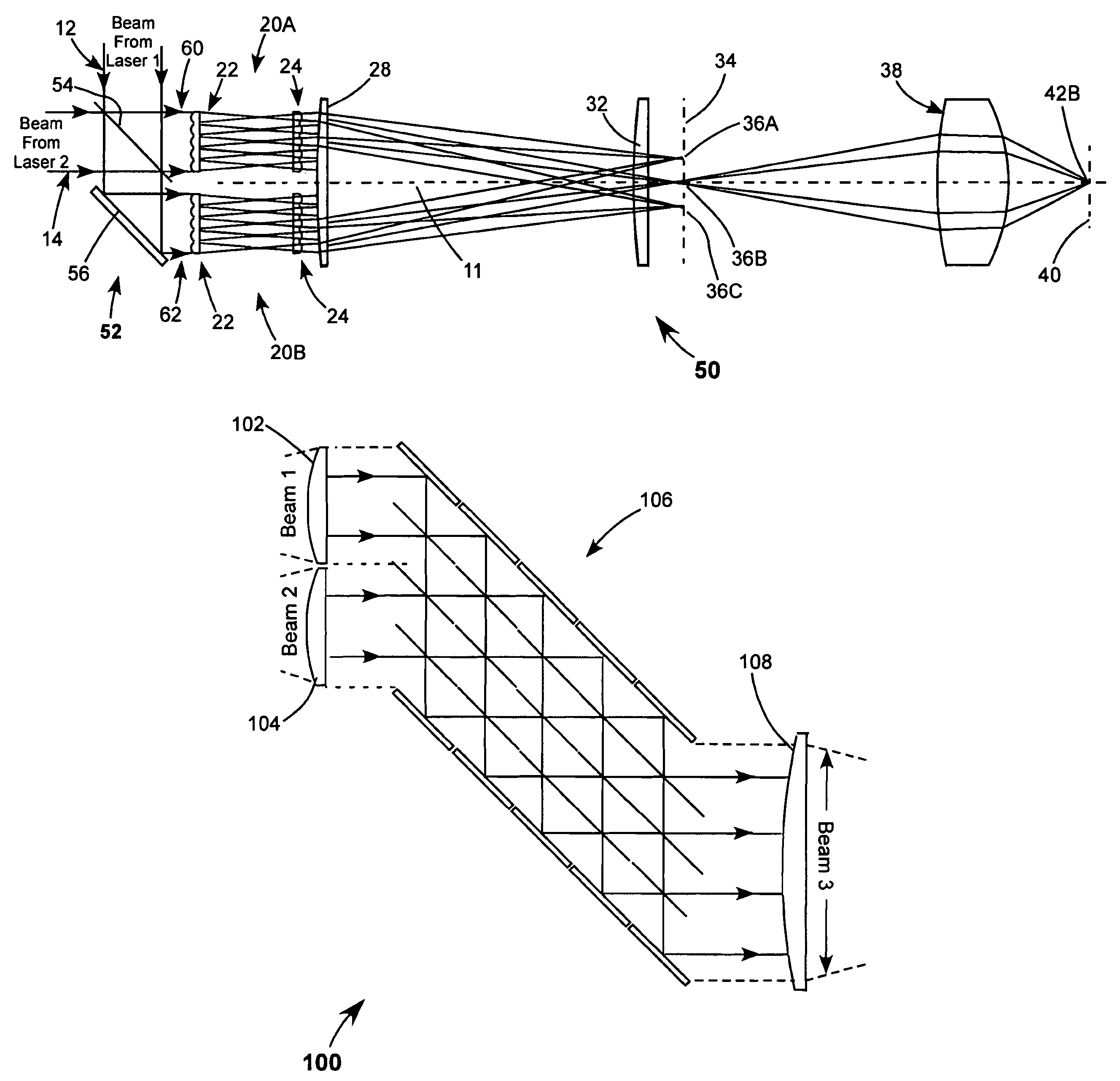
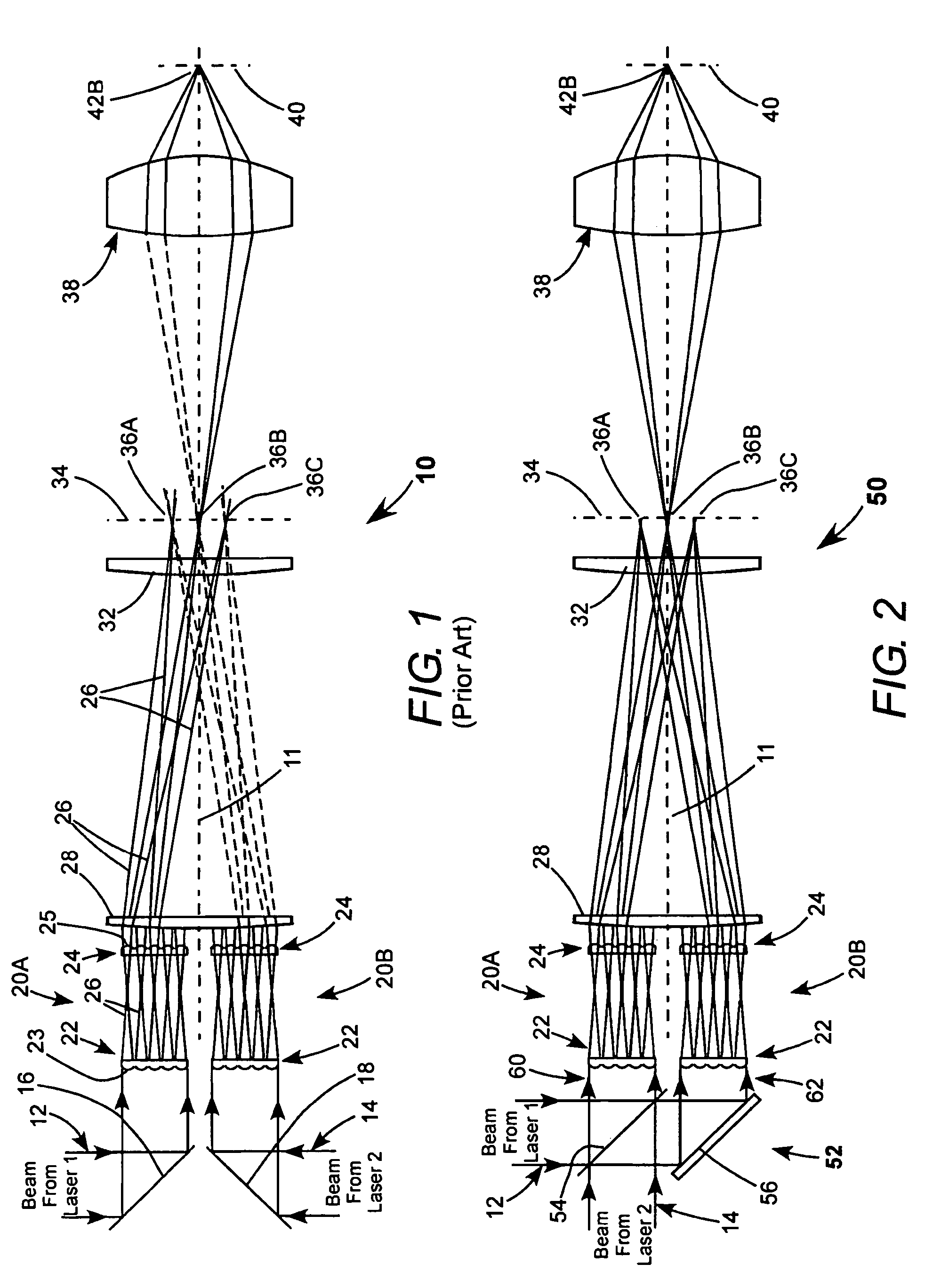
[0033]Referring now to the drawings, wherein like features are designated by like reference numerals, FIG. 2 schematically illustrates a photomask imaging arrangement 50 including one embodiment of a beam-coupling method in accordance with the present invention. The method is described with reference to the prior-art beam-coupling method depicted in apparatus of FIG. 1 for convenience of description and to highlight advantages of the inventive method.

[0034]In apparatus 50, the arrangement of homogenizers 20A and 20B, collecting lens 28, and field lens 32 for causing two beams to be homogenized, and obliquely coupled in plane 34, is similar to that of apparatus 10 of FIG. 1. In apparatus 50, however, beams 12 and 14 from the two lasers are incident on an inventive optical arrangement that may be described as a beam-mixer or pre-coupler 52, including a beamsplitter 54 and a mirror 56 in this embodiment thereof. This beam-mixer provides, from beams 12 and 14 that have individual charac...


PUM


Abstract

In a photomask projection system, a photomask mask is illuminated by light from two lasers. A beam from one of the lasers is mixed with a beam from the other laser to provide two mixed beams each containing of portion of the beams from both lasers. The mixed beams are directed at an angle to each other and intersect on the photomask.

Description

PRIORITY[0001]This application claims priority from U.S. Provisional Application Ser. No. 60 / 652,080, filed Feb. 11, 2005, the disclosure of which is incorporated herein by reference.TECHNICAL FIELD OF THE INVENTION[0002]The present invention relates in general to coupling of laser beams. The invention relates in particular to equalizing parameters of laser beams to be coupled either before the beams are coupled or as the beams are coupled.DISCUSSION OF BACKGROUND ART[0003]Coupling of two or more laser beams often becomes necessary if a beam from a single laser cannot provide sufficient power (if the beam is CW beam), sufficient average power (if the beam is a beam from a repetitively pulsed laser), or sufficient peak power (if the beam is repetitively-pulsed beam or an individually-pulsed beam) for a particular application.[0004]Beam combining methods may be summarized as being of two different types. One type, which is often referred to as temporal interleaving, is used exclusivel...

Claims


Application Information

Patent Timeline
Patent Type & Authority Patents(United States)
IPC IPC(8): G02B27/14G02B27/10
CPCG02B27/0905G02B27/0961G02B27/0977G02B19/0028G02B19/0095G02B19/0052G02B27/283
Inventor WINDPASSINGER, ROMANSIMON, FRANK
Owner COHERENT GMBH
Why Eureka
Try Eureka