Connector with header connector and socket connector that are mechanically and electrically connected with each other

a technology of socket connector and header connector, which is applied in the direction of securing/insulating coupling contact members, fixed connections, coupling device connections, etc., can solve the problems of adding unwanted load to the contact, and achieve the effect of shortening increasing the size of the socket contact, and lengthening the insert length of the header conta

Active Publication Date: 2008-08-12
MATSUSHITA ELECTRIC WORKS LTD
View PDF10 Cites 67 Cited by
  • Summary
  • Abstract
  • Description
  • Claims
  • Application Information

AI Technical Summary

Benefits of technology

[0009]In another aspect of the present invention, the socket housing further comprises a slot that has facing surfaces as said facing surfaces in the cavity. The slot is formed at the bottom and another facing surfaces in the cavity, and includes a through hole at the bottom side. In addition, the socket contact is put in the slot, and the retention grooves and the guiding grooves are opened toward the insert direction. According to this invention, it is possible to increase the size of the socket contact in the insert direction without increasing the size of the socket housing in the direction as compared with the structure that a socket contact comes in contact with the bottom of a connection cavity. Accordingly, it is possible to lengthen the insert length of the header contact into the contact section of the socket contact. In addition, since the socket housing can be compacted without shortening the size of the socket contact, in case that the socket housing is compacted in that way, it is possible to prevent wear-out caused by reduction of the socket contact.
[0010]In another aspect of the present invention, each of the guiding grooves has a width wider than the thickness of the one end of the contact section and has a buffer gap 269c′ at side of the neighboring retention groove when the wall fixing the header contact is not inserted into the cavity. According to this invention, unwanted load can be prevented from adding to the socket contact when the wall fixing the header contact is inserted into the cavity and pulled out thereof. It is also possible to prevent excessive deformation of the socket contact.
[0011]In another aspect of the present invention, the both sides of the one end of the contact section are formed with a pair of guide projections that are guided along the guiding grooves and substantially come in contact with the guiding grooves, respectively. In addition, the both sides of the part of the fixed section are formed with a pair of guide projections guided along the retention grooves and a pair of retention projections pressed into the retention grooves, respectively. According to this invention, the socket contact can be properly fixed to the socket housing.
[0012]In another aspect of the present invention, the header housing further includes another wall along the insert direction, and the end face of the another wall is formed with a rack that sticks out along the insert direction. The socket housing further includes a receiving cavity in which said another wall is received. The bottom of the receiving cavity is formed with a pair of rack stoppers that stick out along the insert direction so that the tip of the rack is sandwiched between the stoppers when the wall fixing the header contact is inserted into the connection cavity. According to this invention, the header housing and the socket housing can be firmly fixed to each other. Moreover, around the rack stoppers each of which receives stress can be reinforced with the thickness thereof, and also molding is simple because of simple structure of drawing.

Problems solved by technology

Moreover, contact condition between the contact 17 and a corresponding contact 12 becomes unstable as well, and also unwanted load is added to the contact 17 when inserted into the connection cavity.

Method used


Image

  • Connector with header connector and socket connector that are mechanically and electrically connected with each other
  • Connector with header connector and socket connector that are mechanically and electrically connected with each other
  • Connector with header connector and socket connector that are mechanically and electrically connected with each other

Examples


Embodiment Construction

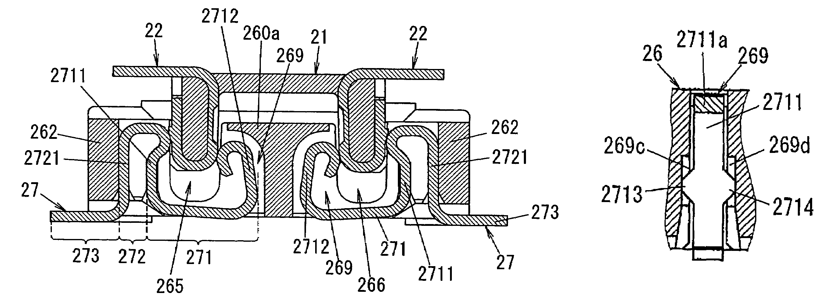
[0024]FIG. 3 shows an embodiment according to the present invention, namely a connector 2. The connector 2 comprises a header connector 20 and a socket connector 25.

[0025]The header connector 20 is constructed with a header housing 21 formed of electrically insulating material such as synthetic resins or the like and header contacts 22 each of which is made of a conductive metal plate.

[0026]As shown in FIGS. 3 and 5, the housing 21 is formed into a slender box shape with a base 210, and four walls (sides) 211-214 along an insert direction. The housing 21 is also provided with attaching terminals 23 soldered to, for example, a printed circuit board at the four corners thereof.

[0027]The contacts 22 are arranged and fixed at specified intervals on the lengthwise walls 211 and 212 of the housing 21 by, for example, insert molding. That is, each contact 22 is bent so that both faces of a lengthwise wall are sandwiched between the bent two parts of the contact 22, and then is fixed on the...


PUM


Abstract

A connector comprising a header connector 20 and a socket connector 25. The connector 25 includes a fixed section 272 that is continuously formed at the tip of one end 2711 of a contact section 271 so that a part 2721 of the section 272 is arranged in parallel with the one end. A housing 26 of the connector 25 sandwiches and retains both sides of the part 2721 between a pair of facing retention grooves, and also sandwiches and receives both sides of the one end 2711 between a pair of facing guiding grooves so that the one end 2711 can move only along facing surfaces including the above each groove.

Description

TECHNICAL FIELD[0001]The invention relates generally to connectors and more particularly to a connector comprising a header connector and a socket connector that are mechanically and electrically connected with each other.BACKGROUND ART[0002]This sort of connector is disclosed in, for example, Japanese Patent Application Publication No. 2004-55463. As shown in FIGS. 1A and 1B, this connector 1 comprises a header connector 10 and a socket connector 15.[0003]The header connector 10 is constructed with a header housing 11 formed of electrically insulating material such as synthetic resins or the like and header contacts 12 each of which is made of a metal plate. The housing 11 is formed into a slender box shape with a base, and four walls (sides) along an insert direction. The contacts 12 are arranged and fixed at specified intervals on lengthwise walls 111 and 112 of the housing 11. That is, each contact 12 is bent so that both faces of a lengthwise wall are sandwiched between the ben...

Claims


Application Information

Patent Timeline
Patent Type & Authority Patents(United States)
IPC IPC(8): H01R12/00H01R12/57
CPCH01R12/716H01R13/41H01R13/639
Inventor KISHI, MASANORIOKURA, KENJI
Owner MATSUSHITA ELECTRIC WORKS LTD
Why Eureka
Try Eureka