Supercharge Your Innovation With Domain-Expert AI Agents!

Optical rotation angle measuring apparatus

a technology of optical rotation angle and measuring apparatus, which is applied in the direction of optical elements, instruments, optical radiation measurement, etc., can solve the problems of large fluctuation range large size and cost and disadvantageous fluctuations of optical rotation angle measuring apparatus using liquid crystal elements, etc., to narrow the fluctuation range and improve phase modulation sensitivity.

Inactive Publication Date: 2008-08-12
CITIZEN WATCH CO LTD
View PDF19 Cites 3 Cited by
  • Summary
  • Abstract
  • Description
  • Claims
  • Application Information

AI Technical Summary

Benefits of technology

[0028]According to the present invention, operations of the first phase modulation section and the second phase modulation section can be stabilized. In addition, since the polarization axes of the first phase modulation section and the second phase modulation section are orthogonal to each other, a predetermined bias signal can be cancelled and only a desired phase modulation amount can be obtained.
[0051]According to the present invention, the signal in the section in which the phase modulation amount of the liquid crystal element is linearly changed is used. The fluctuation in the difference between the signal supplied to the liquid crystal element and that supplied to the second liquid crystal element can be a fluctuation in a very narrow range. It is, therefore, possible to narrow the range of this fluctuation and improve phase modulation sensitivity.

Problems solved by technology

If the liquid crystal element 1931 modulates the phase of only one polarized component, linearly polarized lights interfere with each other.
This disadvantageously makes the optical rotation angle measuring apparatus large in size and expensive.
However, the optical rotation angle measuring apparatus using the liquid crystal element is disadvantageous in large fluctuations due to external environment such as temperature or atmospheric pressure.
Such an apparatus is similarly disadvantageously made large in size, and expensive.
However, the conventional techniques do not at all disclose this respect, so that the conventional techniques have a disadvantage in that stable and precise measurement cannot be ensured.

Method used


Image

  • Optical rotation angle measuring apparatus
  • Optical rotation angle measuring apparatus
  • Optical rotation angle measuring apparatus

Examples


first embodiment

(Hardware Configuration of Optical Rotation Angle Measuring Apparatus)

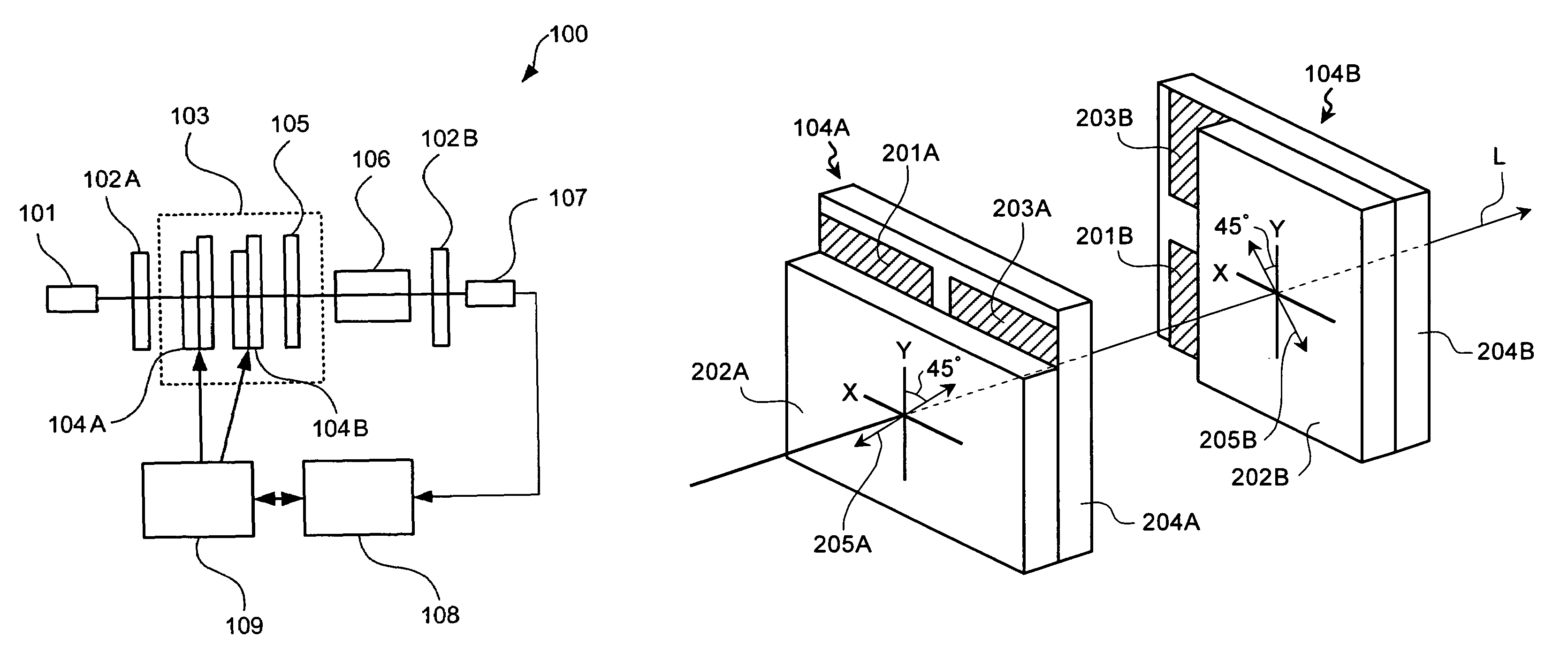
[0074]A hardware configuration of an optical rotation angle measuring apparatus according to a first embodiment of the present invention will be explained. FIG. 1 is a block diagram of the hardware configuration of the optical rotation angle measuring apparatus according to the first embodiment of the present invention. An optical rotation angle measuring apparatus 100 includes a light source 101, a polarizer 102A, an azimuth rotator 103, a polarizer 102B, a photodiode 107, an arithmetic processor 108, and a liquid crystal driver 109.

[0075]The light source 101 includes, for example, a laser diode, a driver circuit, an oscillator circuit, and a DC power supply. The driver circuit drives the laser diode to have a single intensity and a single frequency. The oscillator circuit outputs a clock signal to the driver circuit. The light source 101 thereby receives a power from the DC power supply and irradiates a laser li...

second embodiment

[0131]A second embodiment of the present invention will be explained. FIG. 8 is a block diagram of a hardware configuration of an optical rotation angle measuring apparatus according to the second embodiment of the present invention. An optical rotation angle measuring apparatus 800 according to the second embodiment is configured so that the sample 106 is held between two quarter-wave plates 105A and 105B on the optical path L. In FIG. 8, like constituent elements as those in the hardware configuration shown in FIG. 1 are denoted by like reference symbols.

[0132]FIG. 8 is a block diagram of the second embodiment. A light-flux emitted from the light source 101 is transformed into a linearly polarized light by the polarizer 102A. The liquid crystal elements 104A and 104B are arranged next to the polarizer 102A. As the liquid crystal elements 104A and 104B, homogenous alignment-type liquid crystal elements are employed. The liquid crystal molecule orientation directions of the liquid c...

third embodiment

[0137]A third embodiment of the present invention will be explained. FIG. 9 is a block diagram of a hardware configuration of an optical rotation angle measuring apparatus according to the third embodiment of the present invention. The two liquid crystal elements 104A and 104B are employed in the optical rotation angle measuring apparatus 800 according to the second embodiment. One liquid crystal element 104 is employed in an optical rotation angle measuring apparatus 900 according to the third embodiment, and the liquid crystal element 104 has a pixel structure. A lens 941 serving as a condensing unit is additionally provided in the apparatus 900, and the photodiode 107 is arranged on a focal plane of the lens 941. In FIG. 9, like constituent elements as those in the hardware configurations shown in FIGS. 1 and 8 are denoted by like reference symbols.

[0138]The liquid crystal element 104 is configured by a plurality of pixels 1005 to 1008 (four pixels in FIG. 10A). FIG. 10A is a fro...


PUM

PropertyMeasurementUnit
optical rotation angle measuringaaaaaaaaaa
phaseaaaaaaaaaa
light intensity detectionaaaaaaaaaa

Abstract

A linearly polarized light output unit (701) outputs a linearly polarized light. A first phase modulation unit (703) includes a first polarization axis and modulates a phase of the linearly polarized light. A second phase modulation unit (704) includes a second polarization axis orthogonal to the first polarization axis and modulates the phase of the linearly polarized light. A signal supply unit (705) supplies a modulation signal (vb) for modulating the phase of the linearly polarized light to one of the phase modulation units. A light intensity detection unit (707) detects an intensity of a light emitted from a phase modulation unit (702), to which the signal is supplied, to a sample (106) that contains an optically active material by causing a polarization plane of the light to be rotated and the light to be transmitted by the sample (106). An optical rotation angle calculation unit (708) calculates an optical rotation angle based on the modulation signal (Vb) and the detected light intensity.

Description

TECHNICAL FIELD[0001]The present invention relates to an optical rotation angle measuring apparatus that measures an optical rotation angle of a sample.BACKGROUND ART[0002]Conventionally, an angle of rotation of a polarization plane rotated by a sample, that is, an optical rotation angle (also referred to as “an optical rotary power”) is calculated from a signal obtained by causing a linearly polarized light to be incident on the sample, causing a light-flux transmitted by the sample to be incident on an analyzer, and photoelectrically converting the light-flux into an electric signal using a photodiode.[0003]Assuming that a gradient of a transmission axis of the analyzer with respect to a transmission axis of a polarizer is θ and that an optical rotation angle by the sample is α, an intensity I of the light received by the photodiode is represented by the following Equation (1): I=T×I0 cos(θ−α)2. In the Equation (1), symbol T denotes transmissivity in consideration of all attenuati...

Claims


Application Information

Patent Timeline
Patent Type & Authority Patents(United States)
IPC IPC(8): G01J4/00G02F1/01G01N21/21
CPCG01N21/21
Inventor MATSUMOTO, KENJIYANO, TAKAKAZUFUKUDA, TADAHIROFUTAKAMI, SHIGERU
Owner CITIZEN WATCH CO LTD
Features
  • R&D
  • Intellectual Property
  • Life Sciences
  • Materials
  • Tech Scout
  • Unparalleled Data Quality
  • Higher Quality Content
  • 60% Fewer Hallucinations
Learn More