Finger sleeve sensor holder

a sensor and finger sleeve technology, applied in the field of holders, can solve the problems that the sensor itself may interfere with the physiological parameter(s), and achieve the effect of facilitating the application of the sensor holder

Active Publication Date: 2008-08-12
DATEX OHMEDA
View PDF19 Cites 43 Cited by
  • Summary
  • Abstract
  • Description
  • Claims
  • Application Information

AI Technical Summary

Benefits of technology

[0008]Once deformed into a desired shape, the plastically deformable member may be elastically deformed to a second shape to provide a retaining force, in the manner of a paper clip, to maintain the sensor holder and a sensor interconnected thereto in contact with a patient appendage. For example, the opposing surfaces of a U-shaped member may be slightly sprung to allow the firm insertion of a patient appendage therebetween. By utilizing the plastically deformable member, the sensor holder of the present invention may be shaped to conform to a variety of patient appendages while providing a customizable fit for that appendage. Furthermore, by utilizing elastic deformation of the shaped member to provide retention force, the sensor holder may be applied to an appendage without the use of adhesives or other connectors. However, an adhesive material may additionally be provided on a patient contact surface to further enhance the retention / holding force of the sensor holder.
[0013]A second aspect of the present invention provides a sensor holder that includes: a deformable backing layer that is plastically deformable from a first configuration to a second configuration; a patient interface layer having a first surface interconnected to the deformable backing layer and a second inside surface for interfacing with a patient appendage; and a sensor recess located on the inside surface of the patient interface layer for selectively receiving a sensor. Prior to application to a patient appendage, the sensor holder may be in any first configuration (e.g., planer, an open U-shape, etc) that allows a patient appendage to be disposed relative to the inside surface of the patient interface layer. In order to be applied to a patient appendage, the deformable backing layer of the sensor holder may then be plastically deformed (i.e., bent) into a second configuration to engage opposing surfaces of a patient appendage. In this regard, the sensor holder may be custom-sized for an appendage. For example, the sensor holder may be bent into a U-shape such that at least a first and second portion of the sensor holder are in an opposing relationship and contacting opposing surfaces of an appendage. As will be appreciated, the appendage may be removed to allow an additional plastic deformation of the deformable backing layer. Upon insertion of the appendage, the opposing surfaces may elastically deform relative to one another allowing those surfaces to apply a compressive retaining force to the patient appendage. If desired, the patient interface layer may further include an adhesive (e.g., covered by a removable release liner). Such an adhesive may be utilized to increase the retention force of the sensor in high patient movement conditions.
[0014]The patient interface layer may be formed of any appropriate material. However, in one embodiment the patient interface layer is formed of a compressible material to provide cushioning between the sensor holder and the appendage of the patient. In this regard, the compressible material may have a compression setting that, upon application of a predetermined pressure to the material, substantially conforms to the surface contacting the compressible material (e.g., a patient's finger). In this regard, the compressible material may have a plurality of void spaces to permit compression. Preferred compressible material is open or closed cell foam, neoprene, rubber, fabric, and composites thereof, with foam being the most preferred. As will be appreciated, use of a compressible material for the patient interface also allows for better sensor holder to appendage conformance, which may provide for improved retaining forces between the sensor holder and to the appendage.
[0018]According to a third aspect of the present invention, a sensor holder is provided for holding a sensor relative to a patient appendage. The sensor holder of the third aspect includes a first member for engaging a first portion of a patient appendage, a second member for engaging a second portion of a patient appendage, and a plastically deformable interconnecting member that interconnects the first member to the second member, wherein at least one of the first and second members for selectively interconnectable to a sensor. The plastically deformable interconnecting member allows selective positioning of the first member relative to the second member and thereby facilitates application of the sensor holder to a wide variety of appendages. Additionally, the plastically deformable interconnecting member is elastically deformable to provide a spring-like retention force to maintain the sensor holder relative to a patient appendage.

Problems solved by technology

For example, if a sensor is held too loosely relative to the tissue it may not function; in contrast, if a sensor is held too tightly to the tissue, the sensor itself may interfere with the physiological parameter(s) it is supposed to monitor.

Method used


Image

  • Finger sleeve sensor holder
  • Finger sleeve sensor holder
  • Finger sleeve sensor holder

Examples


first embodiment

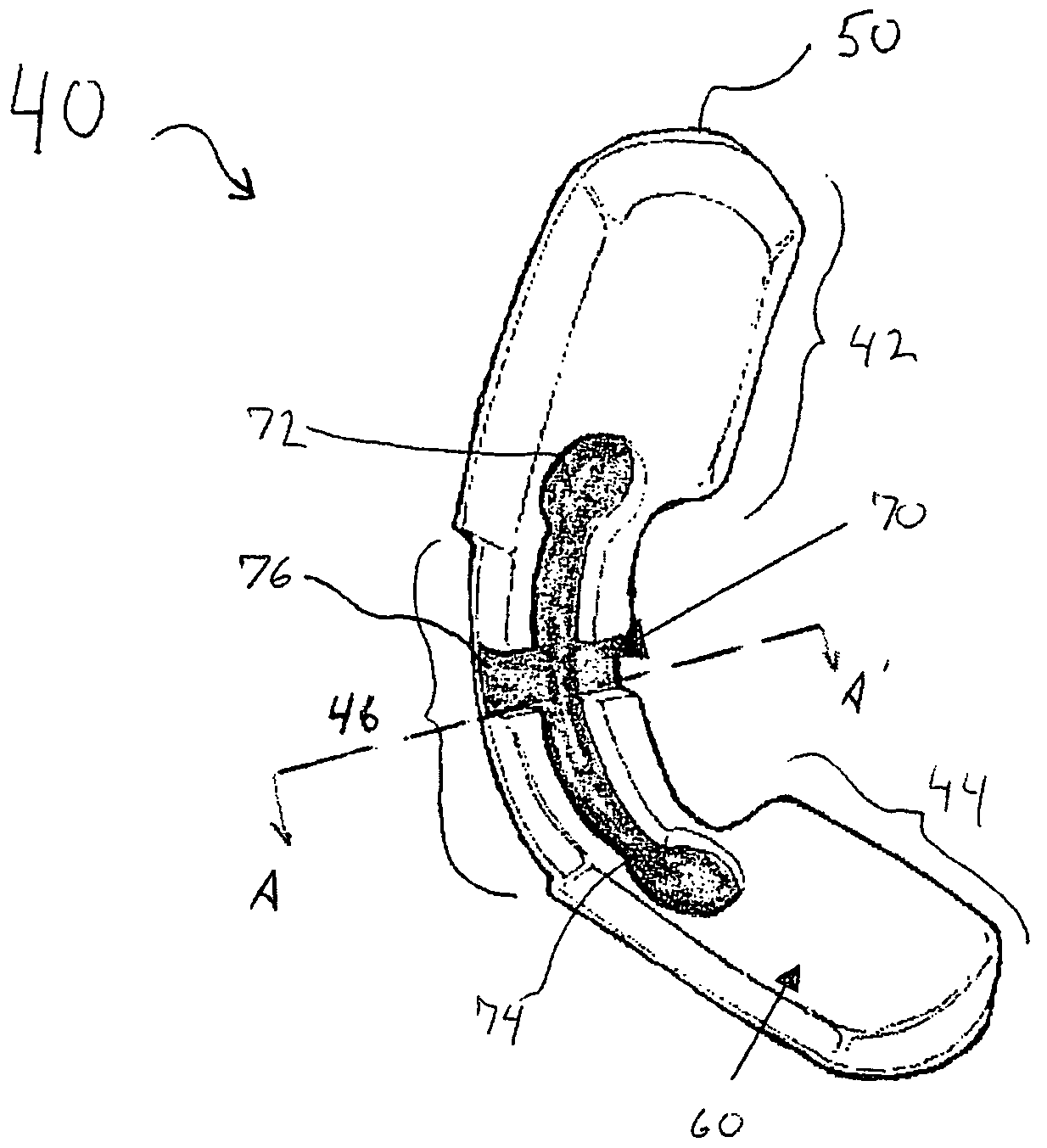
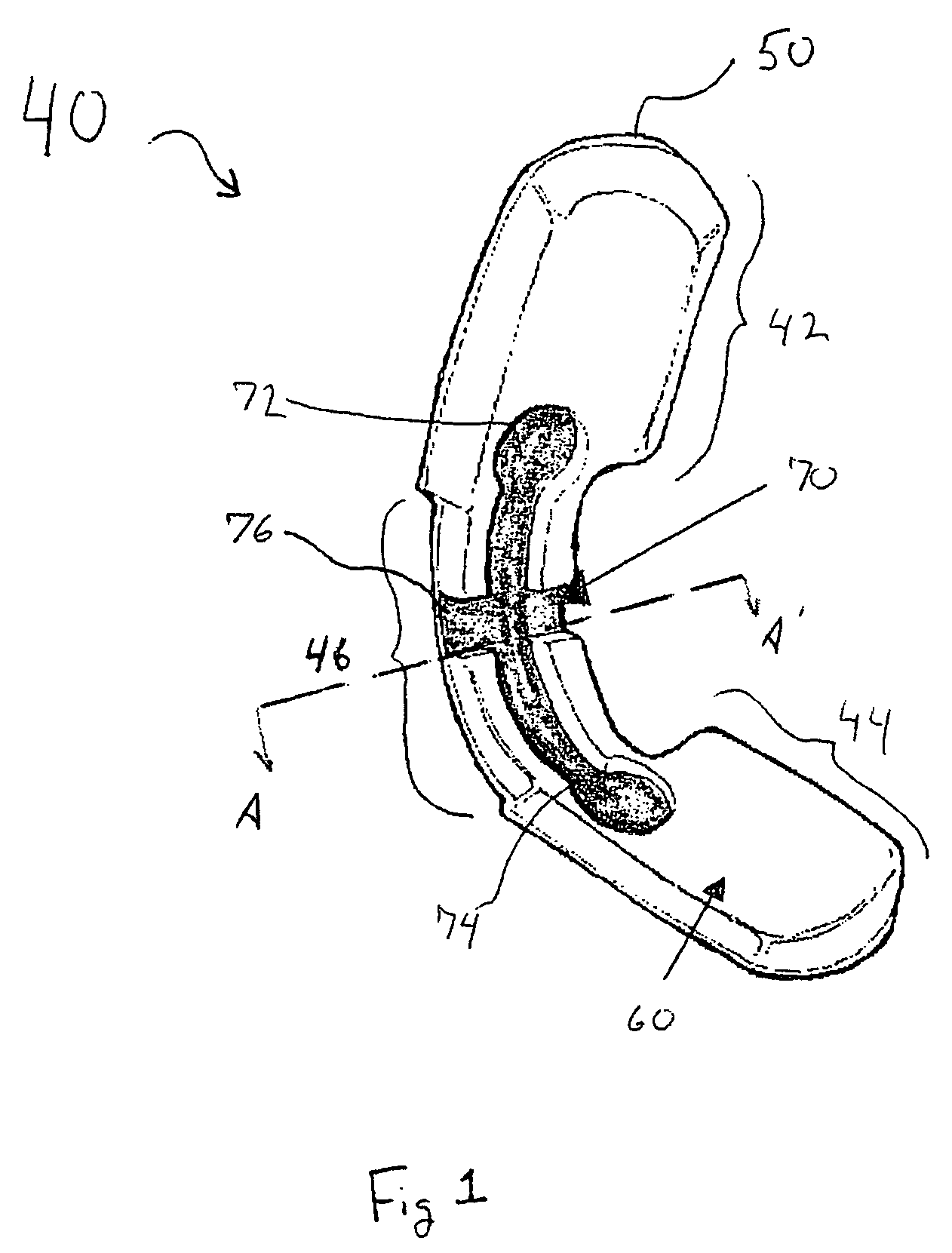
[0036]FIG. 1 shows the sensor holder 40. The sensor holder 40 contains a deformable backing layer 50 that makes up the outside surface or “shell” of the sensor holder 40. In accordance with the present invention, the deformable backing layer is both plastically deformable to allow the sensor holder to maintain a desired shape and elastically deformable to provide a resilient spring-like holding force, as will be more fully discussed herein. Interconnected to the inside surface of the deformable backing layer 50 is a patient interface layer 60 for providing a gentle interface with a patient appendage. The inside (i.e., patient side) surface of the patient interface layer 60 contains a sensor recess 70 that is utilized to selectively receive a sensor and hold the sensor relative to the sensor holder. As shown in FIG. 1, the sensor holder 40 is formed substantially as an elongate member that is particularly apt for application to a finger (see FIG. 4). Referring again to FIG. 1, it is ...

third embodiment

[0048]FIG. 8 shows a deformable sensor holder 200 in accordance with the present invention. In this embodiment, the sensor holder 200 contains first and second members 210, 220 that are substantially rigid in comparison with a deformable interconnecting member 230. As will be appreciated, in this embodiment, all deformation of the sensor holder 200 is isolated in the interconnecting member 230. This allows the first and second members to be pre-formed to interface with a particular patient appendage. As shown, the first and second members 210, 220 are formed to matingly receive a finger and in this regard each contain a finger trough 240. As will be appreciated, utilizing the finger troughs 240, the sensor holder 200 is able to better conform to a patient finger and to provide added light blocking characteristics for a sensor that may be inserted within the troughs 240.


PUM


Abstract

A conformable medical sensor is provided that has particular applicability for positioning a pulse oximeter sensor relative to a patient appendage. In one embodiment, the sensor holder includes a patient engaging member that is plastically deformable to permit the sensor holder to be conformed to the patient appendage, and plastically deformable to provide a retention force relative to the patient appendage. For example, the engaging member may be bent into a first shape that disposes first and second portions of the sensor holder into an opposing relationship the for receiving a patient appendage therebetween. Once deformed, the engaging member may be elastically deformed to a second shape to provide a retention force so as to maintain the sensor holder and a sensor interconnected thereto in contact with the patient appendage. In another embodiment, and the sensor holder may include a deformable backing layer that is plastically and elastically deformable, as described above, together with a patient interface layer having a recess located for the receipt of the sensor therein.

Description

FIELD OF THE INVENTION[0001]The present invention is generally directed to a holder for positioning a medical sensor relative to patient tissue. More specifically, the present invention is directed to a conformable holder for use in securely positioning a medical sensor relative to a patient appendage without requiring the use of adhesives or separate securing devices.BACKGROUND[0002]In many medical applications it is desirable to hold one or more medical sensors in contact with a patient's tissue such that various non-invasive measurements of physiological parameters may be non-invasively monitored. For example, medical sensors may be held in contact with a patient's tissue to non-invasively determine pulse rates, blood pressure, temperature, and / or blood oxygenation levels. Common to many non-invasive medical sensors is the need to properly position the sensor relative to the patient's tissue to ensure proper sensor operation. For example, if a sensor is held too loosely relative ...

Claims


Application Information

Patent Timeline
Patent Type & Authority Patents(United States)
IPC IPC(8): A61B5/00
CPCA61B5/14552A61B5/6816A61B5/6838A61B5/6833A61B5/6826
Inventor MEDINA, LILY ANJANETTE
Owner DATEX OHMEDA
Why Eureka
Try Eureka