[0008] Once deformed into a desired shape, the plastically deformable member may be elastically deformed to a second shape to provide a retaining force, in the manner of a paper clip, to maintain the sensor holder and a sensor interconnected thereto in contact with a patient appendage. For example, the opposing surfaces of a U-shaped member may be slightly sprung to allow the firm
insertion of a patient appendage therebetween. By utilizing the plastically deformable member, the sensor holder of the present invention may be shaped to conform to a variety of patient appendages while providing a customizable fit for that appendage. Furthermore, by utilizing elastic deformation of the shaped member to provide retention force, the sensor holder may be applied to an appendage without the use of adhesives or other connectors. However, an
adhesive material may additionally be provided on a patient contact surface to further enhance the retention / holding force of the sensor holder.
[0013] A second aspect of the present invention provides a sensor holder that includes: a deformable backing layer that is plastically deformable from a first configuration to a second configuration; a patient
interface layer having a first surface interconnected to the deformable backing layer and a second inside surface for
interfacing with a patient appendage; and a sensor recess located on the inside surface of the patient
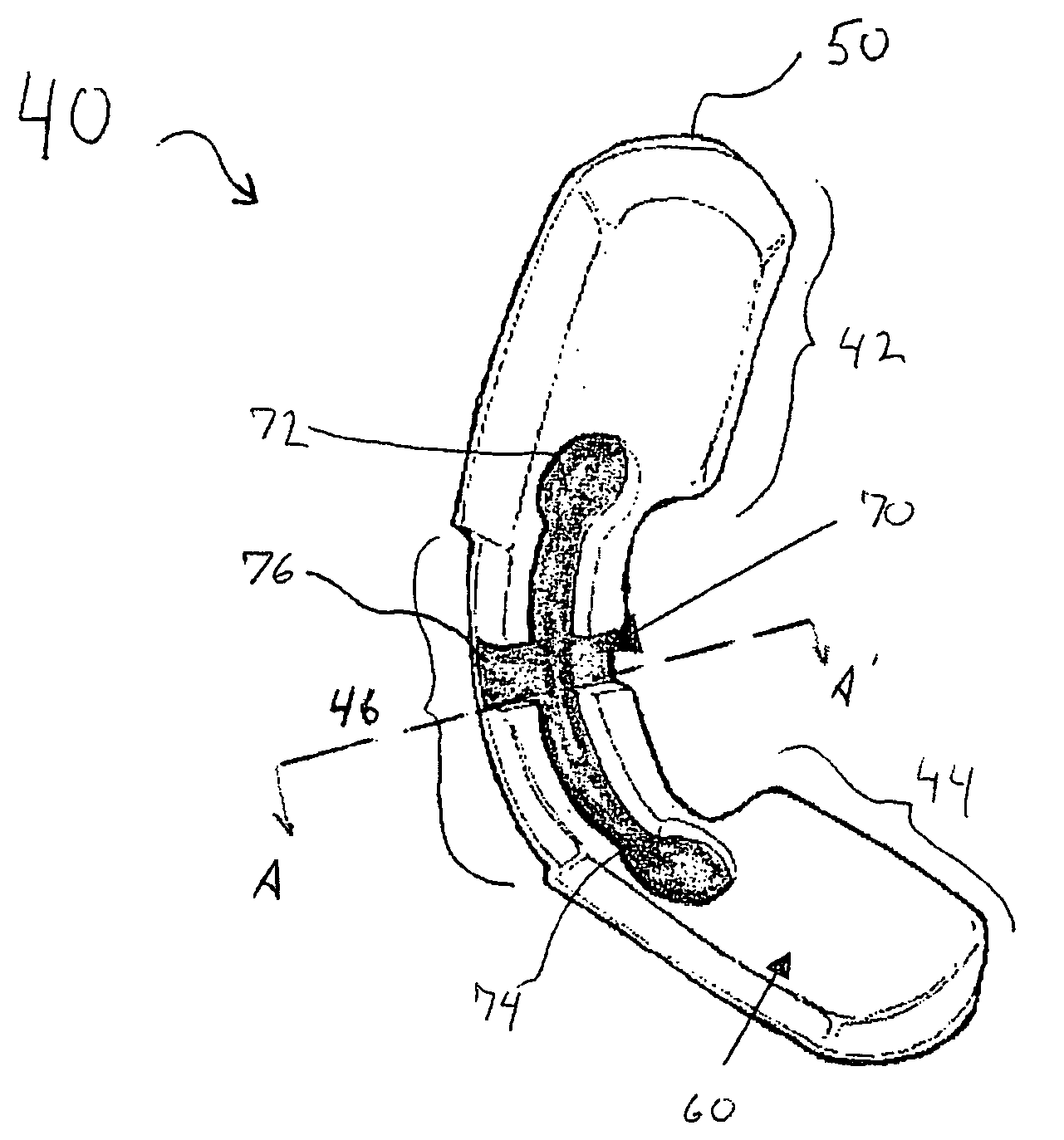
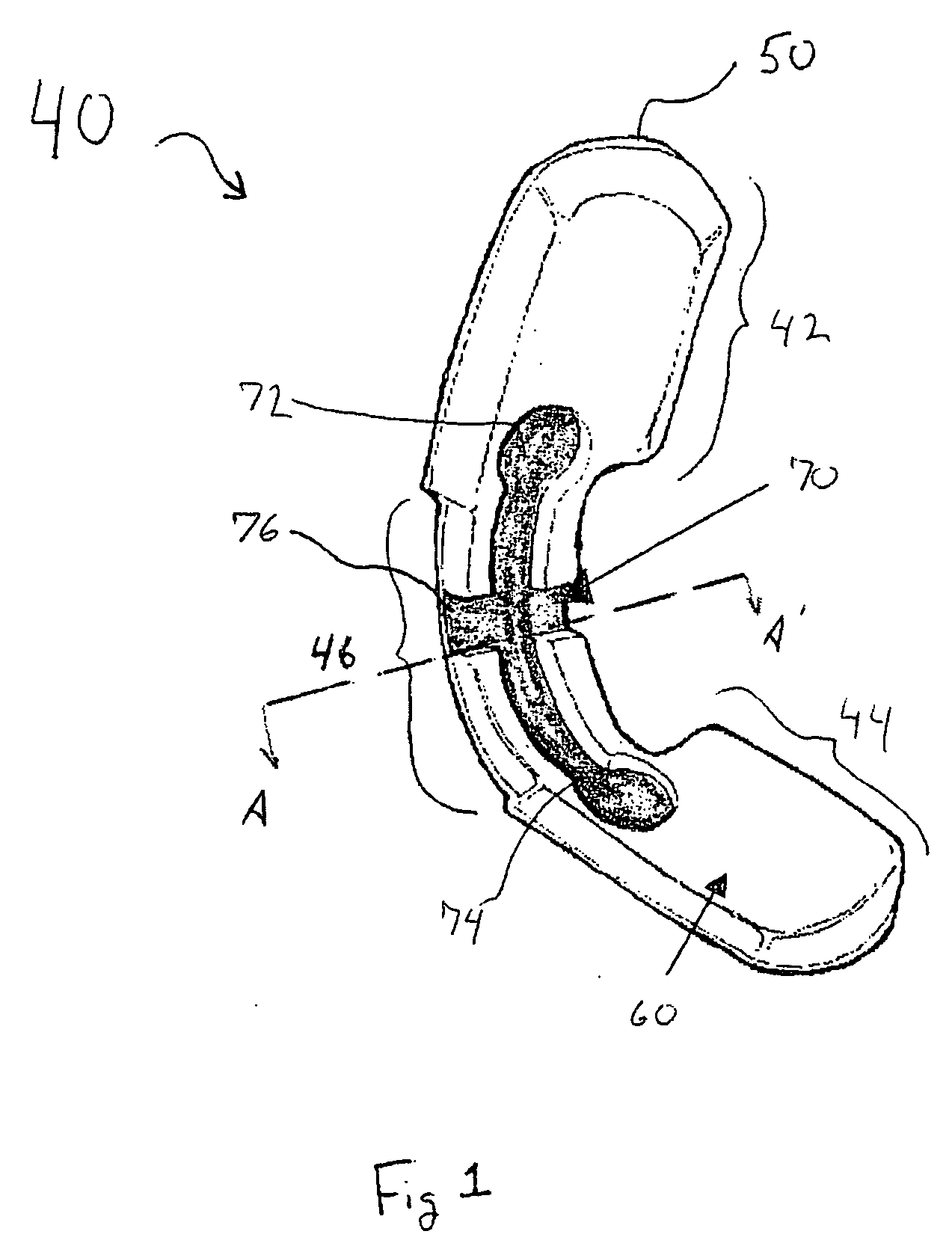
interface layer for selectively receiving a sensor. Prior to application to a patient appendage, the sensor holder may be in any first configuration (e.g., planer, an open U-shape, etc) that allows a patient appendage to be disposed relative to the inside surface of the patient interface layer. In order to be applied to a patient appendage, the deformable backing layer of the sensor holder may then be plastically deformed (i.e., bent) into a second configuration to engage opposing surfaces of a patient appendage. In this regard, the sensor holder may be custom-sized for an appendage. For example, the sensor holder may be bent into a U-shape such that at least a first and second portion of the sensor holder are in an opposing relationship and contacting opposing surfaces of an appendage. As will be appreciated, the appendage may be removed to allow an additional plastic deformation of the deformable backing layer. Upon
insertion of the appendage, the opposing surfaces may elastically deform relative to one another allowing those surfaces to apply a compressive retaining force to the patient appendage. If desired, the patient interface layer may further include an
adhesive (e.g., covered by a removable
release liner). Such an
adhesive may be utilized to increase the retention force of the sensor in high patient movement conditions.
[0014] The patient interface layer may be formed of any appropriate material. However, in one embodiment the patient interface layer is formed of a
compressible material to provide
cushioning between the sensor holder and the appendage of the patient. In this regard, the
compressible material may have a compression setting that, upon application of a predetermined pressure to the material, substantially conforms to the surface contacting the
compressible material (e.g., a patient's finger). In this regard, the compressible material may have a plurality of void spaces to permit compression. Preferred compressible material is open or
closed cell foam,
neoprene, rubber, fabric, and composites thereof, with foam being the most preferred. As will be appreciated, use of a compressible material for the patient interface also allows for better sensor holder to appendage conformance, which may provide for improved retaining forces between the sensor holder and to the appendage.
[0018] According to a third aspect of the present invention, a sensor holder is provided for holding a sensor relative to a patient appendage. The sensor holder of the third aspect includes a first member for engaging a first portion of a patient appendage, a second member for engaging a second portion of a patient appendage, and a plastically deformable interconnecting member that interconnects the first member to the second member, wherein at least one of the first and second members for selectively interconnectable to a sensor. The plastically deformable interconnecting member allows selective positioning of the first member relative to the second member and thereby facilitates application of the sensor holder to a wide variety of appendages. Additionally, the plastically deformable interconnecting member is elastically deformable to provide a spring-like retention force to maintain the sensor holder relative to a patient appendage.

