Floorcloth attached suction brush for vacuum cleaner

a vacuum cleaner and suction brush technology, applied in the field of floorcloth attached suction cleaners, can solve the problems of inconvenient user operation, ineffective removal of stains or foreign matter, and smooth operation of the impeller, so as to reduce noise, increase the rotational torque of the driving fan, and reduce the effect of nois

Inactive Publication Date: 2008-08-19
SAMSUNG GWANGJU ELECTRONICS CO LTD
View PDF11 Cites 10 Cited by
  • Summary
  • Abstract
  • Description
  • Claims
  • Application Information

AI Technical Summary

Benefits of technology

[0014]A cross-flow turbofan may be applied as the driving fan. In addition, the driving fan has plural vanes which are arranged away from the center of the driving fan as far as possible and along the circumferential direction, whereby the rotational torque for the driving fan can be increased through a flywheel effect when the driving fan rotates and thus the rotational force of the driving fan can be increased.
[0015]The two pairs of bevel gears may be spiral bevel gears, which can reduce noise.

Problems solved by technology

However, such a vacuum cleaner has a disadvantage in that it is inefficient in removing stains or foreign matter matted to the surface to be cleaned.
That inconveniences the user who must first remove dust accumulated on the floor using a cleaner, and then directly wipe the surface using a floorcloth to remove the foreign matter or stain remaining on the surface.
Therefore, dust accumulates between the impeller and its driving shaft for driving the impeller, as well as on the impeller, and thus inhibiting smooth operation of the impeller, thereby limiting the number of revolutions of the wet floorcloth and reducing the wiping effect.
In addition, because the impeller has a cone shape, the height of which increases as it approaches the center of the impeller due to the characteristics of the impeller, and the plural spur gears are used so as to transfer power, it is difficult to configure the suction brush in a compact form.
In addition, because the plural spur gears are employed, it is necessary to provide a bearing for each gear, thereby increasing and the number of components manufacturing costs.
Furthermore, the spur gears, generate loud noise when the gears are driven.
However, this suction brush has a problem in that if hair or the like is caught in the turbine shaft or the like, the turbine stops, and thus the rotation of the floorcloth is stopped, whereby the wiping function cannot be used.

Method used


Image

  • Floorcloth attached suction brush for vacuum cleaner
  • Floorcloth attached suction brush for vacuum cleaner
  • Floorcloth attached suction brush for vacuum cleaner

Examples


Embodiment Construction

[0023]Hereinbelow, the preferred embodiments of the present invention are described in detail with reference to accompanying drawings. In the following description, a detailed description of known functions and configurations incorporated herein will be omitted when it may make the subject matter of the present invention rather unclear.

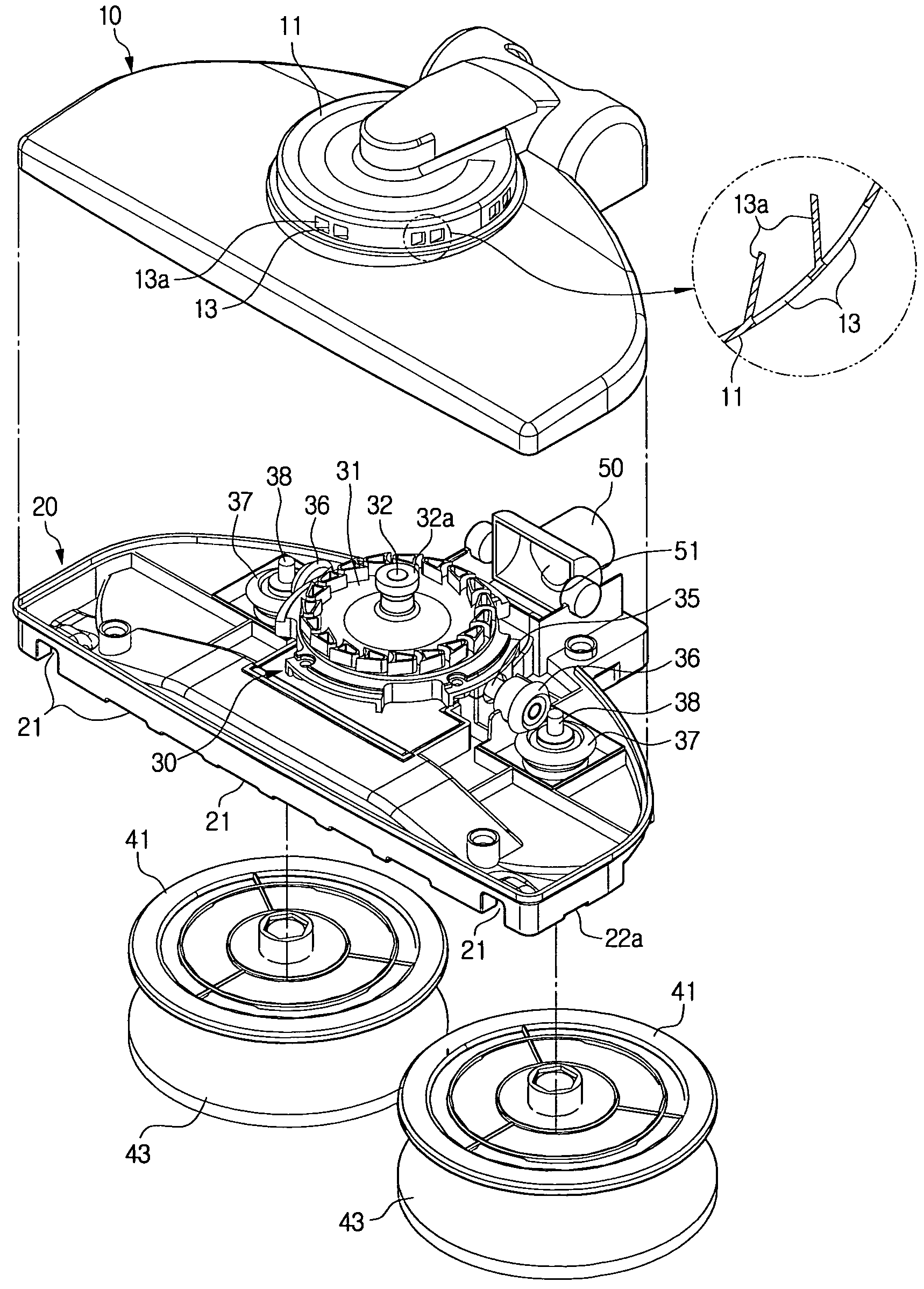
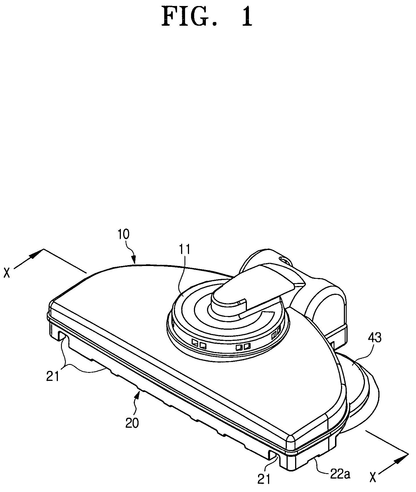
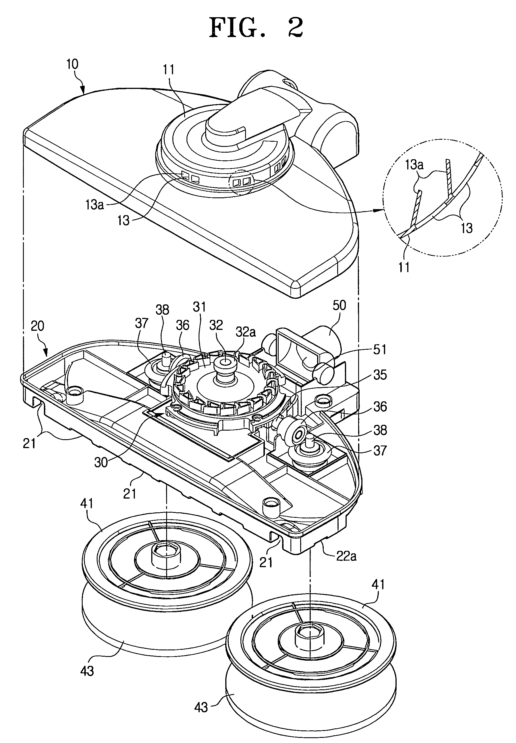
[0024]FIG. 1 is a perspective view showing a floorcloth attached suction brush of a vacuum cleaner according to an embodiment of the present invention in an assembled state, FIG. 2 is an exploded perspective view the floorcloth attached suction brush of a vacuum cleaner according to the embodiment of the present invention, FIG. 3 is a cross-sectional view taken along line X-X of FIG. 1, FIG. 4 is a perspective view showing, partially in cross-section, a two-way air flow path of the floorcloth attached suction brush of a vacuum cleaner according to the present invention, and FIG. 5 is a bottom view of the floorcloth attached suction brush of a vacuum c...


PUM


Abstract

A suction brush that includes a body in communication with a dust collection apparatus of a vacuum cleaner and having a main suction port formed through a bottom of the body, and a cover for covering the top of the body, the cover having auxiliary suction ports. A pair of floorcloth support plates are rotatably mounted on the bottom of the body, with floorcloths that are detachably attached to the bottom surfaces of the floorcloth support plates, respectively. A floorcloth rotation unit is mounted in the body so as to rotate the pair of floorcloth support plates. The suction brush also includes a first air suction flow path for guiding air, which is introduced through the main suction port, to the rear side of the body, and a second air suction flow path for guiding air, which is introduced through the auxiliary suction ports to the rear side of the body.

Description

REFERENCE TO RELATED APPLICATION[0001]This application claims the benefit of Korean Patent Application No. 2005-91920, field on Sep. 30, 2005, with the Korean Intellectual Property Office, the disclosure of which is incorporated herein by reference.FIELD OF THE INVENTION[0002]The present invention relates to a floorcloth attached suction cleaner to be used with a vacuum cleaner.BACKGROUND OF THE INVENTION[0003]In general, a vacuum cleaner is an appliance for cleaning by suctioning dust or dirt from a surface using suction force generated by a vacuum motor while moving a suction brush along the surface. Such a vacuum cleaner is somewhat efficient in removing dust scattered on a surfaced to be cleaned. However, such a vacuum cleaner has a disadvantage in that it is inefficient in removing stains or foreign matter matted to the surface to be cleaned. That inconveniences the user who must first remove dust accumulated on the floor using a cleaner, and then directly wipe the surface usin...

Claims


Application Information

Patent Timeline
Patent Type & Authority Patents(United States)
IPC IPC(8): A47L5/00
CPCA47L9/0472A47L9/0416A47L11/20A47L9/02
Inventor OH, JANG-KEUN
Owner SAMSUNG GWANGJU ELECTRONICS CO LTD
Why Eureka
Try Eureka