Packaging device for covering and sealing cover film onto tray

a packaging device and cover film technology, applied in the field of packaging devices, can solve the problems of large vertical movement of the sealing base, obstacle to the welding between the flange and the cover film, etc., and achieve the effect of preventing the difficulty of sealing the film

Inactive Publication Date: 2008-08-19
IBARAKI SEIKI
View PDF6 Cites 11 Cited by
  • Summary
  • Abstract
  • Description
  • Claims
  • Application Information

AI Technical Summary

Benefits of technology

[0008]In this device, a sealer and a sealing frame positioned above and below the tray conveyance path perform a box motion, and cover film is welded by the sealer and the sealing frame onto a tray in which a packaged item is accommodated in a mounded fashion. In this, the first lift mechanism pushes the sealing base upwards until a position where the upper surface of the sealing base makes contact with the lower surface of the flange of a tray mounted on the deck plate, and the second lift mechanism pushes the sealer downwards until a position where it makes contact with the upper surface of the flange of the tray supported by the sealing base, thereby welding the cover film to the flange. Therefore, since the tension of the cover film that acts on the packaged item is received by the deck plate carrying the tray, then it is possible to prevent difficulties with sealing of the film due to bending of the flange of the tray as a result of the tension of the cover film, or problems such as breaking of the flange.

Problems solved by technology

However, since this device causes the tray to press against an upper-positioned sealing frame, by means of a box motion operation of the lower sealing base only, the amount of vertical movement of the sealing base is large, and the bottom face of the tray becomes separated from the receiving plate which supports it.
In this separated state, the tension in the film acts directly downwards on the tray, through the packaged item accommodated in a mounded fashion in the tray, and therefore, depending on the circumstances, the flange of the tray may break, or the flange may be bent backwards due to the load, thus presenting an obstacle to the welding between the flange and the cover film.

Method used


Image

  • Packaging device for covering and sealing cover film onto tray
  • Packaging device for covering and sealing cover film onto tray
  • Packaging device for covering and sealing cover film onto tray

Examples


embodiment 1

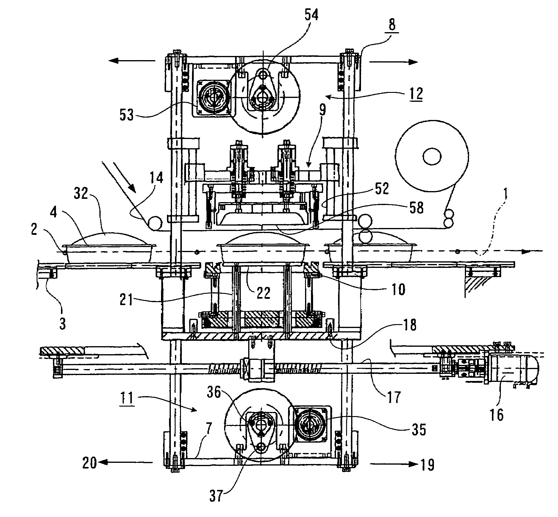
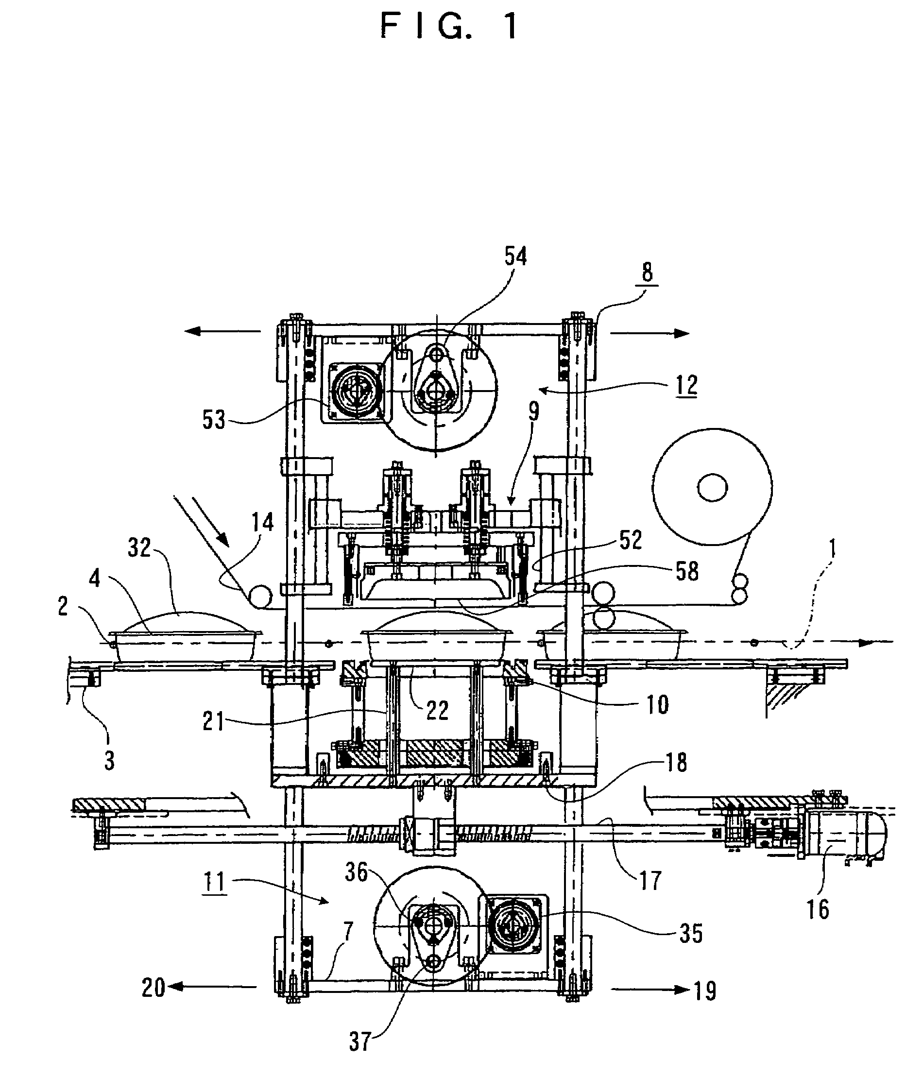
[0021]FIG. 3 shows a general side view of the device, in which touch bars 2 disposed equidistantly on endless chains 1 cause trays 4 to advance at equidistant intervals in the direction of the arrow, along the upper surface of a horizontal conveyance path 3, by the rotational movement of the chains 1. A general frame 8 comprising four corner pillar members 5, a ceiling plate 6 provided on top of these pillar members 5, and a base plate 7 provided below the pillar members 5, is composed in such a manner that a sealing frame set 9 and a sealing base 10 are disposed respectively in upper and lower regions of the general frame 8, and the seal base 10 and the sealing frame set 9 are moved upwards and downwards by means of a first lift mechanism 11 and a second lift mechanism 12, respectively. A band-shaped cover film 14 wound and held on a first reel 13 moves at the same speed as the chains 1 through the lower region of the sealing frame set 9, and it is wound up onto a second reel 15.

[0...

embodiment 2

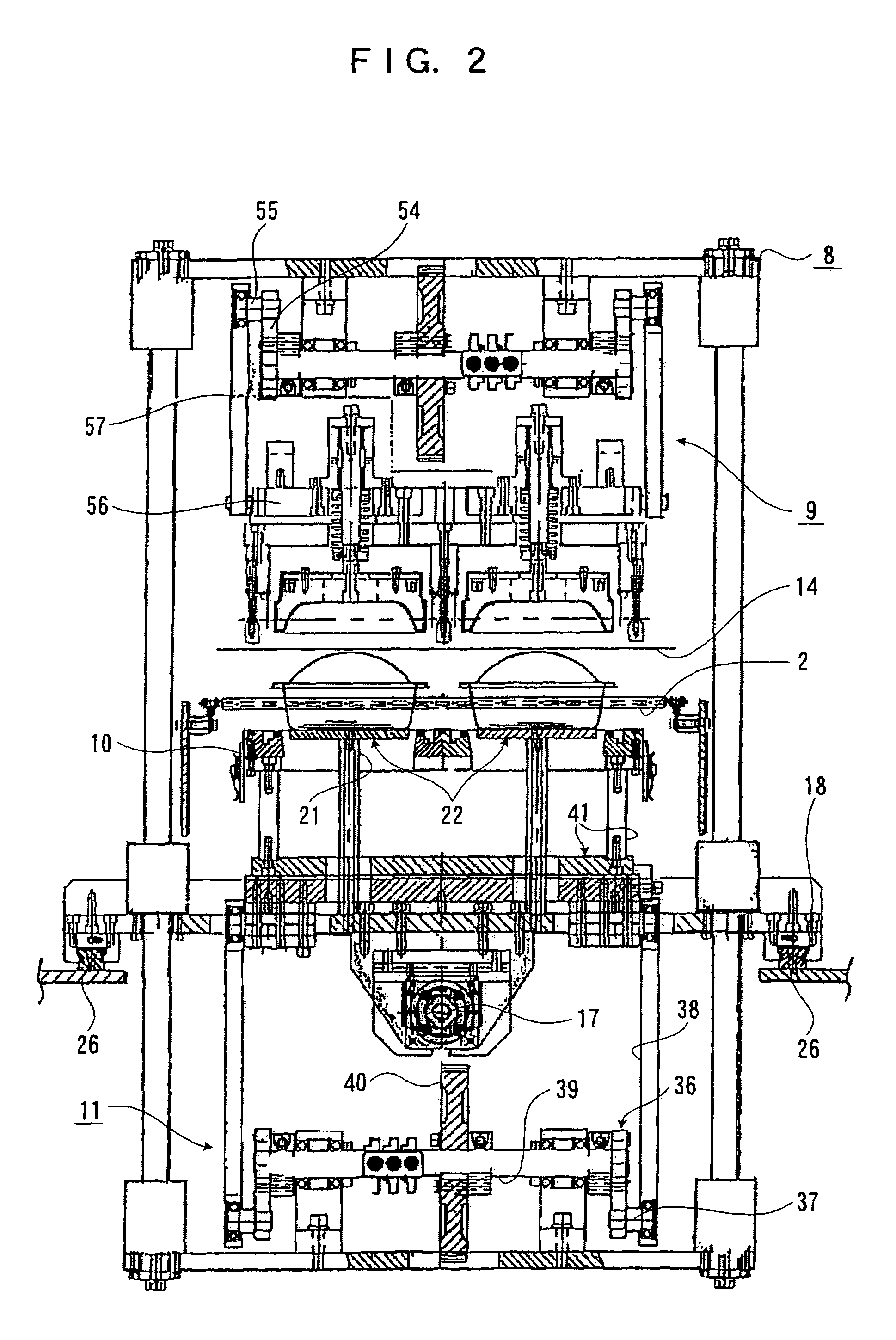
[0036]FIG. 12 shows an embodiment in which the lower-positioned sealing base 10 and the upper-position sealing frame set 9 have different lifting mechanisms, and taking the lower-positioned sealing base 10 as an example, the lift mechanism is formed by a fluid cylinder 77 fixed to the intermediate plate 18. In order that the upper limit of the lifting movement of the sealing base 10 is always restricted by the lower face portion of the flange 33 on the tray 4 which is mounted on the deck plate 22 in accordance with the height of the tray 4, a stopper 79 is provided on the lower side of the piston rod 78, in a position which can be changed along the rod 78, and a variable stopper 80 is also provided on the rod 78 in the upper portion of the cylinder. Furthermore, this composition may also be adopted for the upper-positioned sealing frame set 9.


PUM


Abstract

A packaging device is provided which prevents trays accommodating packaged items from being broken due to the tension in a film acting from above. The sealing base and the sealer perform a box motion by the combination of the back and forth movement of the general frame, and the upward and downward movement of the sealing base and the sealer, and the film is welded onto the flange of the tray while in movement. In this case, by setting the upper limit of the sealing base to the lower surface of the flange of the tray, it is possible for the deck plate to receive the tension of the film acting on the tray through the packaged item.

Description

BACKGROUND OF THE INVENTION[0001]1. Field of the Invention[0002]The present invention relates to a packaging device which stretches and covers a cover film onto a packaged item accommodated in a mounded fashion in a tray, and welds the film onto the flange section of the tray, in the conveyance path of the tray in a conveyor line.[0003]2. Description of the Related Art[0004]The invention disclosed in U.S. Pat. No. 6,834,476B presented by the same applicants as the present case is a packaging device for covering and sealing a cover film onto a tray, in which a sealing frame is moved back and forth reciprocally above the conveyance path of a band-shaped cover film, and a sealing base performs a box motion operation in conjunction with the reciprocal movement of the sealing frame, a tray together with a packaged item being pushed upwards by the upward movement in the box motion operation of the sealing base, the film thus being stretched by the upward pushing of the packaged item, and ...

Claims


Application Information

Patent Timeline
Patent Type & Authority Patents(United States)
IPC IPC(8): B65B51/00B65B53/00
CPCB65B7/164
Inventor KONISHI, KAZUO
Owner IBARAKI SEIKI
Why Eureka
Try Eureka