Gas turbine engine fuel control system and regulating valves therefor

Active Publication Date: 2008-08-19
GOODRICH CONTROL SYST LTD
View PDF16 Cites 6 Cited by
  • Summary
  • Abstract
  • Description
  • Claims
  • Application Information

AI Technical Summary

Benefits of technology

[0010]When a fluid flow control valve is used as a metering valve in a gas turbine engine fuel control system there is commonly provided a separate valve which is opened as the metering valve is shut, to return high pressure fuel to a drain line, thereby to reduce system pressure. It is desirable t

Problems solved by technology

Additionally, high engine operating temperature during reheat operation may cause the fuel in the reheat system to boil and to empty the system when reheat is shut off.
If the system is allowed to empty, or partly empty, it will not respond sufficiently quickly when reheat is

Method used


Image

  • Gas turbine engine fuel control system and regulating valves therefor
  • Gas turbine engine fuel control system and regulating valves therefor
  • Gas turbine engine fuel control system and regulating valves therefor

Examples


Example

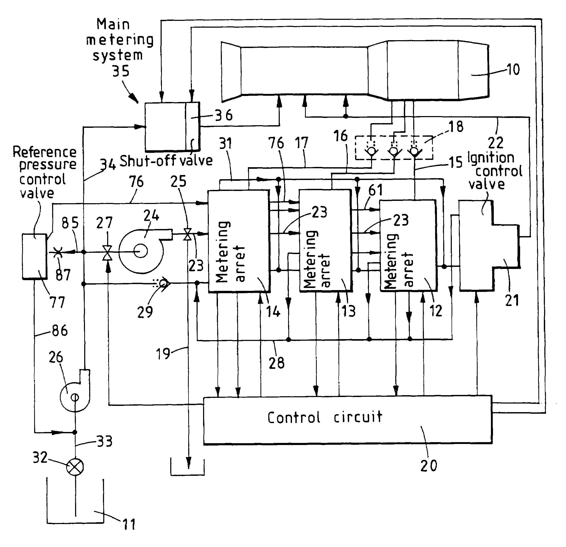
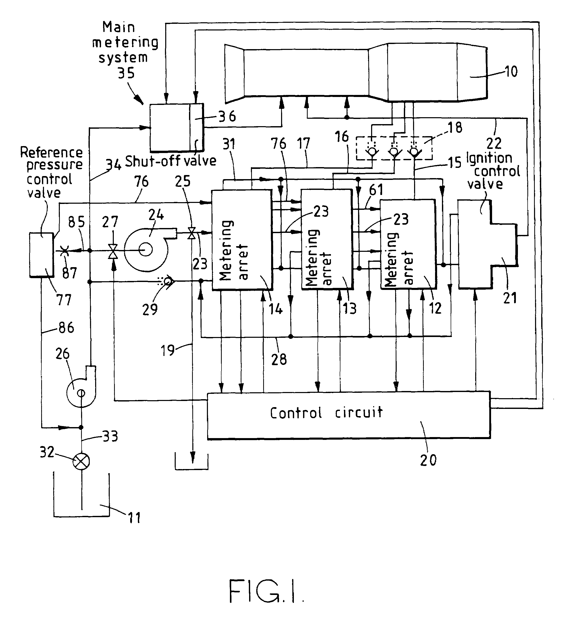
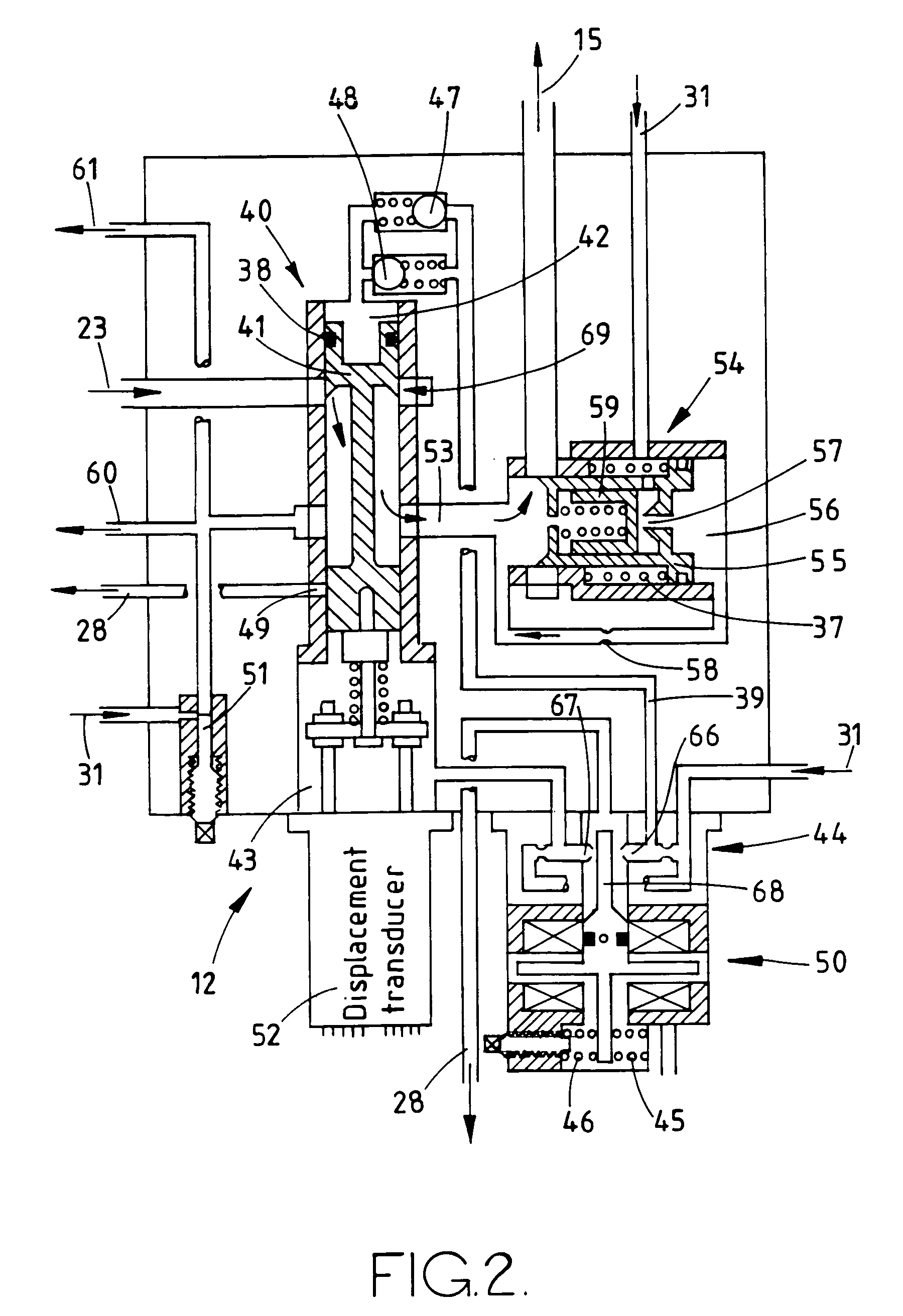
[0018]The gas turbine engine 10, shown in FIG. 1, has three groups of reheat burners, designated primary, bypass and core burners respectively. Fuel for these burners is supplied from a tank 11 by way of metering arrangements 12, 13 and 14 respectively. Outlet passages 15, 16, 17 for the arrangements 12, 13, 14 respectively pass to the engine 10 by way of an arrangement of spring-loaded shut-off valves 18. These valves 18 lift open at a predetermined pressure difference and act, in a manner to be described, as pressure relief valves during shut down of the reheat system. The arrangements 12, 13 and 14 are shown in more detail in FIGS. 2 to 4 respectively and are responsive to signals from an electrical control circuit 20. A device 21 is also responsive to control signals from the circuit 20 to deliver a measured quantity of fuel on a line 22 to the engine 10 to transfer flame from the engine combustion chamber to the reheat burners when the reheat system is switched on.

[0019]The met...


PUM


Abstract

A fuel control system for reheat burners of a gas turbine engine has a plurality of metering valves for respective burners, and throttle valves in series with the respective metering valves. A pressure regulating valve is provided for introducing pressurized fuel into fuel manifolds downstream of the respective throttle valves when the metering and throttle valves are shut. The pressure regulating valve also acts to relieve pressure in low pressure parts of the system when the latter is closed down and to prevent excessive temperature rise at the inlet of a fuel supply pump. The metering valves include pressure return ports which communicate with the metering valve outlets when those valves are shut.

Description

BACKGROUND OF THE INVENTION[0001]1. Field of the Invention[0002]This invention relates to valves for regulating fluid flows and fluid pressures, and to gas turbine engine fuel control systems incorporating such valves.[0003]2. Discussion of Prior Art[0004]It is known to provide metering valves for fluids in which a control element is moved in response to variations in a servo-pressure, the servo-pressure being regulated by a valve which is energised by an electric force motor. It is a disadvantage of such known valves that failure of the force motor or its current supply may result in rapid change in the servo-pressure and consequent rapid movement of the valve control element away from its previously selected position. The present invention describes a metering valve arrangement in which this disadvantage is overcome.SUMMARY OF THE INVENTION[0005]Reheat systems for gas turbine engines are not normally operated for the whole time that the engine is running. Additionally, high engine...

Claims


Application Information

Patent Timeline
IPC IPC(8): B64D27/00F02K3/10
CPCF02C7/232F02C9/263F16K47/04F16K17/196F16K31/363F16K17/06
Inventor SMITH, TREVOR S
Owner GOODRICH CONTROL SYST LTD
Why Eureka
Try Eureka