Inkjet printer with delivery chamber

a technology of delivery chamber and printer, which is applied in the field of inkjet printer, can solve the problems of increasing the size of the device to be mounted, increasing the manufacturing cost, and the damper unit equipped with the plurality of damper chambers suffering from these problems, and achieves the effects of short time, improved maneuverability, and compact siz

Inactive Publication Date: 2008-08-19
BROTHER KOGYO KK
View PDF31 Cites 13 Cited by
  • Summary
  • Abstract
  • Description
  • Claims
  • Application Information

AI Technical Summary

Benefits of technology

[0119]In the inkjet printer constructed according to any one of the above-described modes (1)-(46), although the delivery chamber is flat or elongated in the direction parallel with the wall which defines the delivery chamber, the flow of the ink within the delivery chamber is stabilized, owing to the positional relationship between the delivery chamber inlet and outlet which are positioned in the respective positions which are substantially diagonal relative to each other. As a result of the stabilization in the ink flow within the delivery chamber, the ink and bubbles contained in the ink can easily flow out of the delivery chamber through the delivery chamber outlet.
[0157]In the leakage checking method according to any one of the above-described modes (47), (48), (84) and (85), the positively or negatively pressurized fluid is supplied into at least two of the first delivery channels (which are located on opposite sides of at least one of the first delivery channels which is other than the at least two of the first delivery channels) and the third delivery channels each of which is held in communication with a corresponding one of the at least two of the first delivery channels. If there is a leakage or communication between each of the at least two of the first delivery channels and any one of the at least one of the first delivery channels (which is other than the at least two of the first delivery channels), the above-described supplied fluid exhibits a pressure change, which is different from that exhibited in case of absence of the leakage. Thus, by detecting the pressure change of the supplied fluid, it is possible to easily and reliably determine if there is a leakage in the at least two of the first delivery channels and the third delivery channels communicated with the at least two of the first delivery channels, i.e., a defect in fluid tightness between the cover member and the outer peripheries of these first and third delivery channels. In the present method, while the at least two of the first delivery channels are simultaneously checked for the leakage, the other of the first delivery channels may be checked independently of each other, or alternatively, may be checked simultaneously with each other if possible.

Problems solved by technology

The arrangement of the damper chambers with the spacing intervals leads to an increase in size of a device to be mounted on the carriage and also an increase in the manufacturing cost due to an increased number of required components.
That is, the damper unit equipped with the plurality of damper chambers suffers from these problems.
Due to the small dimension in its height, there is encountered a delay of delivery of the ink in a region which is deviated from a shorted route of the ink flow from an inlet of the lower damper chamber to an outlet of the lower damper chamber.
In addition to such a regional poor flow of the ink, the arrangement suffers from a lack of stability in the flow of the ink in the entirety of the lower damper chamber.
Such a phenomenon is problematic when a liquid (e.g., an ink, a solution that is temporally stored during transportation of the inkjet printer as a product) is initially introduced into the ink passage, since the introduced liquid is stopped before reaching a downstream end of the ink passage.
That is, in absence of a certain arrangement enabling the bubbles to be immediately discharged from the damper chamber through the outlet, the bubbles remain in the damper chamber, and the bubbles are delivered together with the ink to the ink delivery channels of the recording head, thereby problematically affecting an ink ejection performance of the inkjet printer.
The thus generated pressure wave is propagated to the recording head, and the propagated pressure wave affects a meniscus formed at each nozzle of the recording head, thereby resulting in a deterioration in a recording quality.
Further, since the above-described bubble trapper unit is constituted by the first and second members which are connected with each other with the net wall being interposed therebetween, namely, since the bubble trapper unit is provided by three members to be combined together, a cumbersome operation is required in its manufacturing process.
Therefore, the trapped bubbles are likely to remain in vicinity of the second filter and grow to become larger in size.
Consequently, the second filter is clogged with the bubbles, thereby impeding flow of the ink through the second filter.
If a required amount of the ink is not delivered toward the recording head, the printer would become incapable of satisfactorily ejecting the ink.
As described above, if the ink having delivered to the recording head contains bubbles, the bubbles contained in the ink would cause failure in the ink ejection and the consequent deterioration in the quality of the printed image.
In this arrangement, if there is a gap between the second member and an end of the partition wall of the first member, there is caused a leakage between two adjacent ink delivery channels which are located on respective opposite sides of the partition wall in question.
In this case, it is not possible to simultaneously check a leakage of the at least one of the ink delivery channels and a leakage of one of the ink delivery channels that is held in communication with the above-described one of the bubble discharging or ink circulation channels including the adjacent part.
Thus, the number of leakage checking steps required for the plurality of ink delivery channels is inevitably increased.
In the printing operation, each time the signal is outputted from the driver circuit to the recording head, a large amount of electric current momentarily flows through the driver circuit, thereby inducing an abrupt increase in temperature at the driver circuit.
The considerable temperature increase caused deterioration and instability in electrical properties of the driver circuit, thereby impeding a stable ejection of the ink.
That is, there is inevitably caused difference between the plurality of ink delivery channels in degree of influence exerted thereto by the generated heat.
This means that the bubble discharging operation has to be executed very frequently.
Further, even where the ink delivery channels are individually or independently subjected to the bubble discharging operation, the required number of times of the execution of the discharging operation is inevitably increased with increase of the number of the ink delivery channels.
In either of theses cases, therefore, the bubble discharging operation has to be executed such a large number of times, resulting in a poor maneuverability of the inkjet printer.
In addition, the large number of times of the execution of the bubble discharging operation leads to an increase in an amount of the ink which is discharged rather than being used for a recording operation.

Method used


Image

  • Inkjet printer with delivery chamber
  • Inkjet printer with delivery chamber
  • Inkjet printer with delivery chamber

Examples


first embodiment

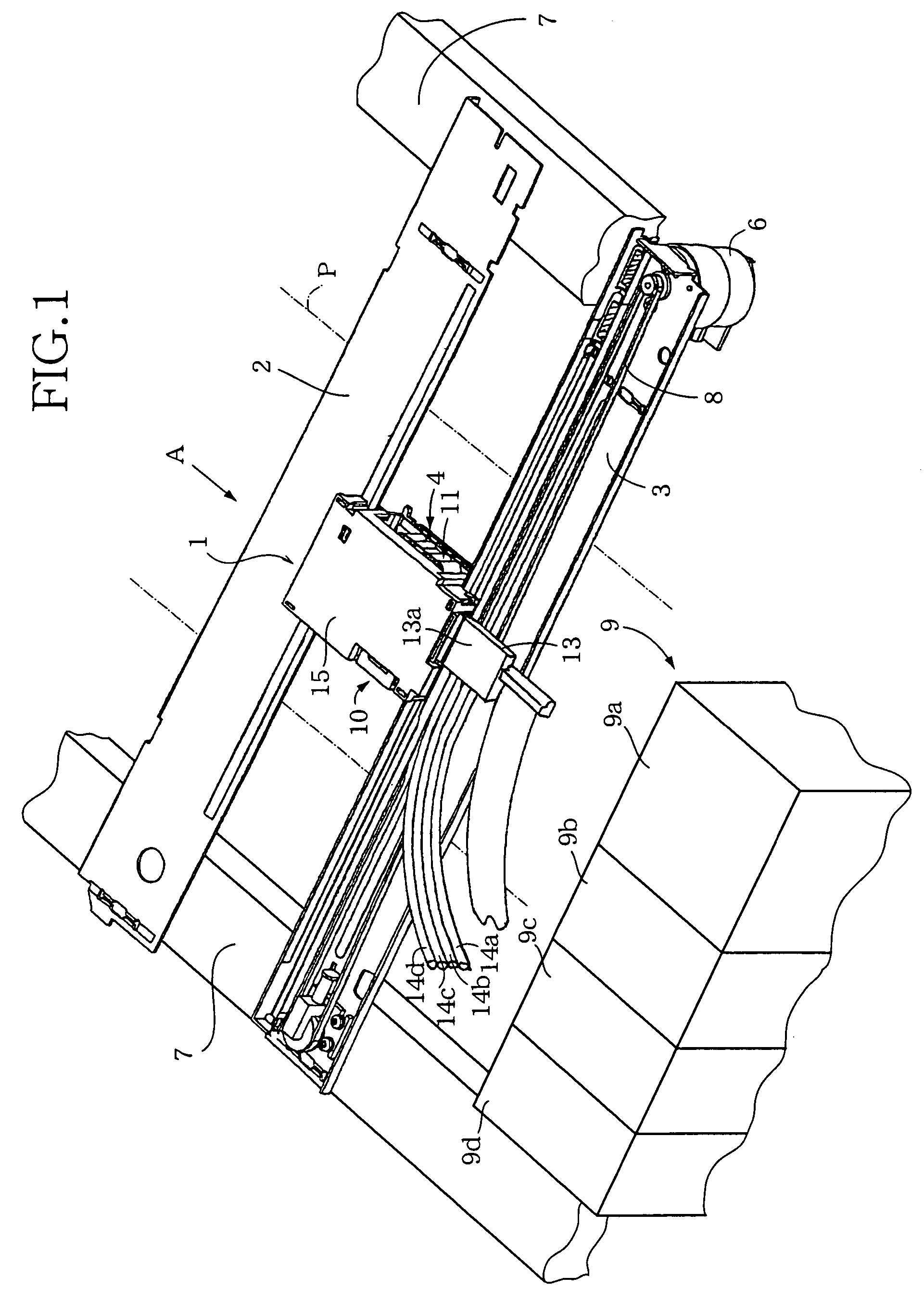
[0159]FIG. 1 is a perspective view of a recording portion of an inkjet printer constructed according to the invention;

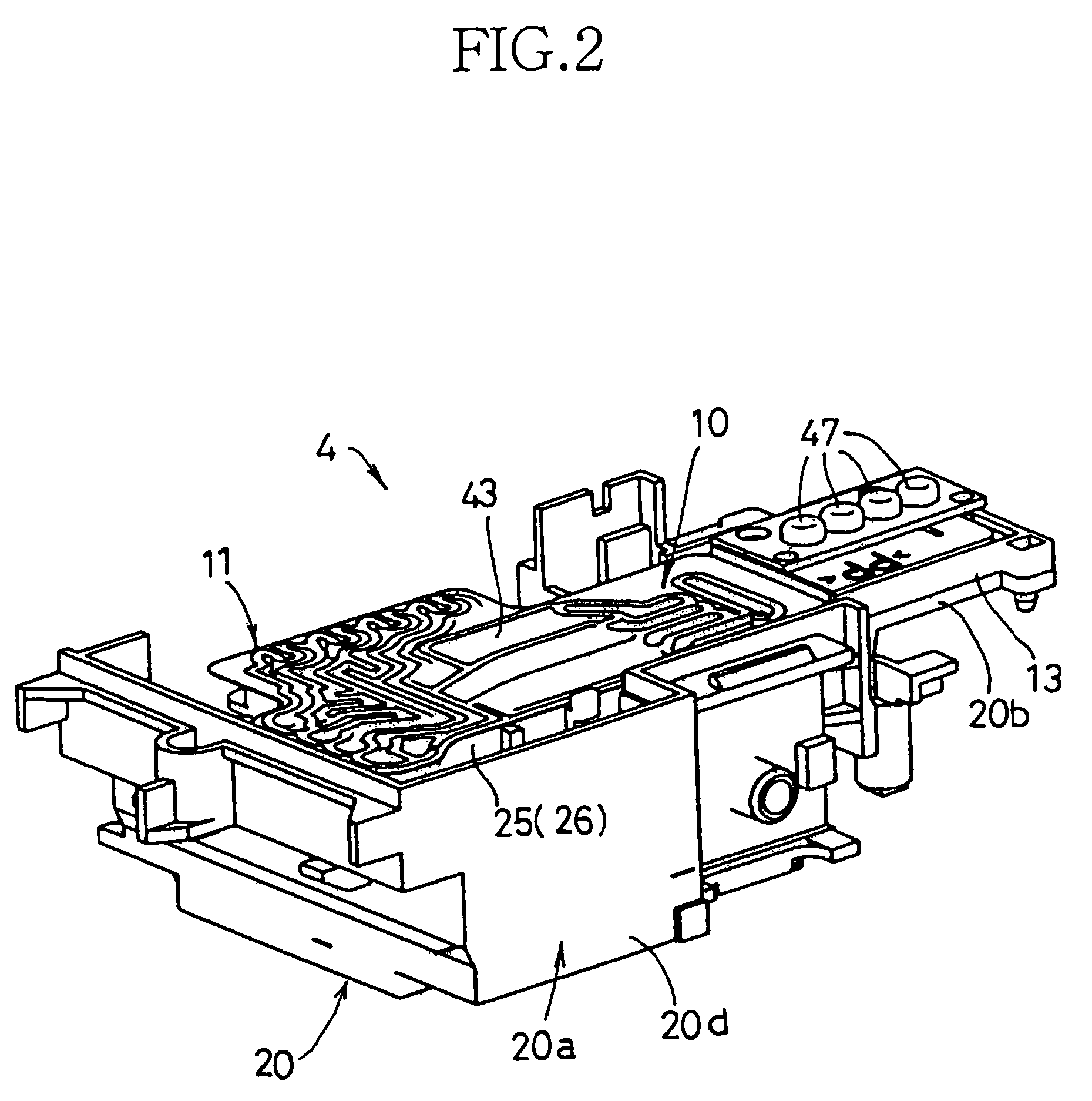
[0160]FIG. 2 is a perspective view of a head unit of the recording portion of the inkjet printer of FIG. 1;

[0161]FIG. 3 is a perspective and exploded view of the head unit of FIG. 2;

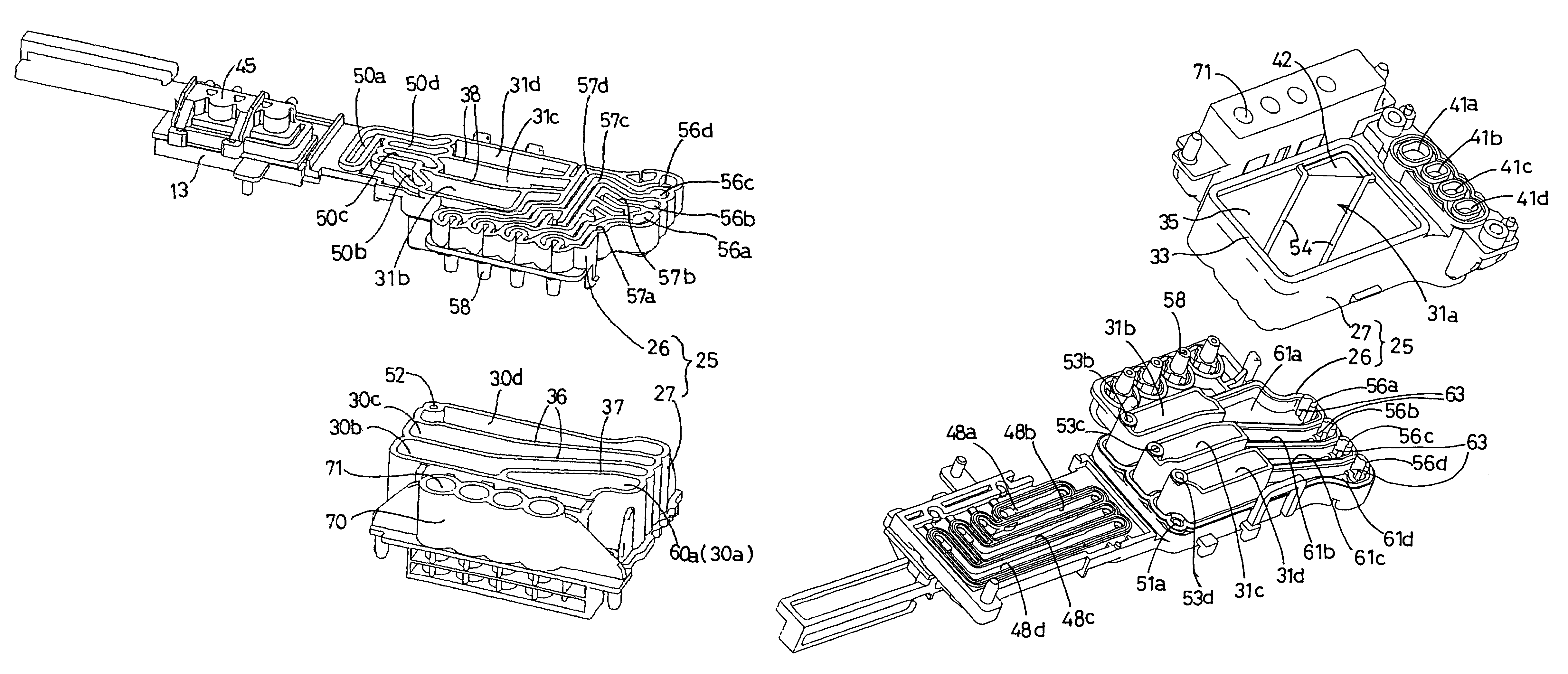
[0162]FIG. 4 is an upper perspective and exploded view of an ink delivery unit of the head unit of FIG. 3;

[0163]FIG. 5 is a lower perspective and exploded view of the ink delivery unit of the head unit of FIG. 3;

[0164]FIG. 6 is another lower perspective and exploded view of the ink delivery unit of the head unit of FIG. 3;

[0165]FIG. 7 is a top-plan view of the head unit of FIG. 3, in absence of an upper flexible film which is to be provided to cover an upper surface of a main body of the ink delivery unit;

[0166]FIG. 8 is a bottom-plan view of the head unit of FIG. 3;

[0167]FIG. 9 is a cross sectional view taken along line 9-9 in FIG. 7;

[0168]FIG. 10 is a top-plan view of the ink delivery u...

second embodiment

[0174]FIG. 16 is a top-plan view of an ink delivery unit of a head unit of an inkjet printer constructed according to the invention, in absence of an upper flexible film which is to be provided to cover an upper surface of a main body of the ink delivery unit;

[0175]FIG. 17 is a bottom-plan view of the ink delivery unit of FIG. 16, in absence of a lower flexible film which is to be provided to cover a lower surface of the main body of the ink delivery unit;

[0176]FIG. 18 is a top-plan view of a lower casing member of the main body of the ink delivery unit of FIG. 16;

[0177]FIG. 19 is a top-plan view of an upper casing member of the main body of the ink delivery unit of FIG. 16;

[0178]FIG. 20 is a horizontal cross section view of the upper casing member of FIG. 19;

[0179]FIG. 21A is a cross sectional view taken along line 21A-21A in FIG. 16;

[0180]FIG. 21B is a cross sectional view taken along line 21B-21B in FIG. 16;

[0181]FIG. 21C is a cross sectional view taken along line 21C-21C in FIG....


PUM


Abstract

An inkjet printer including: (a) a recording head operable to eject an ink onto a recording medium so as to perform a recording operation on the recording medium; (b) an ink source unit provided to store the ink that is to be supplied to the recording head; and (c) an ink delivery unit provided to delivery the ink supplied from the ink source unit, to the recording head. The ink delivery unit has a delivery chamber which has a delivery chamber inlet and a delivery chamber outlet, such that the ink can be delivered through the delivery chamber inlet from the ink source unit, and such that the ink can be delivered through the delivery chamber outlet toward the recording head. The delivery chamber is defined by a wall held in substantially parallel with a horizontal plane, and is elongated in a direction parallel with the wall. The delivery chamber inlet and outlet of the delivery chamber are positioned in respective positions which are substantially diagonal relative to each other.

Description

[0001]This application is based on Japanese Patent Applications No. 2004-080388 filed on Mar. 19, 2004, No. 2004-082364 filed on Mar. 22, 2004, No. 2004-084746 filed on Mar. 23, 2004, No. 2004-092215 filed on Mar. 26, 2004 and Nos. 2004-095226 and 2004-096802 filed on Mar. 29, 2004, the contents of which are incorporated hereinto by reference.BACKGROUND OF THE INVENTION[0002]1. Field of the Invention[0003]The present invention relates to an inkjet printer including (i) a recording head operable to eject ink onto a recording medium so as to perform a recording operation on the recording medium, and (ii) an ink source unit provided to store the ink that is to be supplied to the recording head.[0004]2. Discussion of Related Art[0005]There is known an inkjet printer of so-called tube supply type in which the ink is supplied via a flexible tube to the recording head mounted on a movable carriage, from an ink supply source fixed in a stationary body of the inkjet printer, as disclosed in ...

Claims


Application Information

Patent Timeline
Patent Type & Authority Patents(United States)
IPC IPC(8): B41J2/17B41J2/175B41J2/19
CPCB41J2/175
Inventor TAKATA, MASAYUKISHIMIZU, YOICHIROOKAZAKI, NAOYAIWATSUKI, KAZUAKI
Owner BROTHER KOGYO KK
Why Eureka
Try Eureka