
Thermoformed frequency selective surface

a frequency selective surface and thermoforming technology, applied in the direction of flexible aerials, resonant antennas, collapsible antenna means, etc., can solve the problems of difficult fabrication, complicated pattern, and no known method for patterning curved surfaces to achieve precise frequency selectivity, etc., to facilitate the mapping of fss from two-dimensional geometry into three-dimensional geometry, the effect of less cost and more accura

Active Publication Date: 2008-08-19
ORBITAL ATK INC
View PDF3 Cites 4 Cited by
  • Summary
  • Abstract
  • Description
  • Claims
  • Application Information

AI Technical Summary

Benefits of technology

[0005]These and other problems are solved by using a three-dimensional FSS fabrication system. In the three-dimensional fabrication system, the element geometry and / or FSS grid geometry can be pre-mapped (or pre-distorted) in two-dimensional form prior to further shaping into a three-dimensional surface. In one embodiment, the FSS elements are pre-positioned to produce a desired element placement in the final shape. In one embodiment, mapping of the FSS from the two-dimensional geometry into the three-dimensional geometry is facilitated by using an elastic substrate, such as, for example, a thermoplastic substrate. Constructing the FSS elements on a relatively flat substrate and then forming the FSS and substrate into a desired three-dimensional shape is less expensive and more accurate than prior-art methods of constructing three-dimensional curved FSS structures.

Problems solved by technology

Curvature in the surface complicates the pattern and makes fabrication difficult.
Currently, there is no known method for patterning curved surfaces to achieve precise frequency selectivity in a cost effective manner.

Method used


Image

  • Thermoformed frequency selective surface
  • Thermoformed frequency selective surface
  • Thermoformed frequency selective surface

Examples


Embodiment Construction

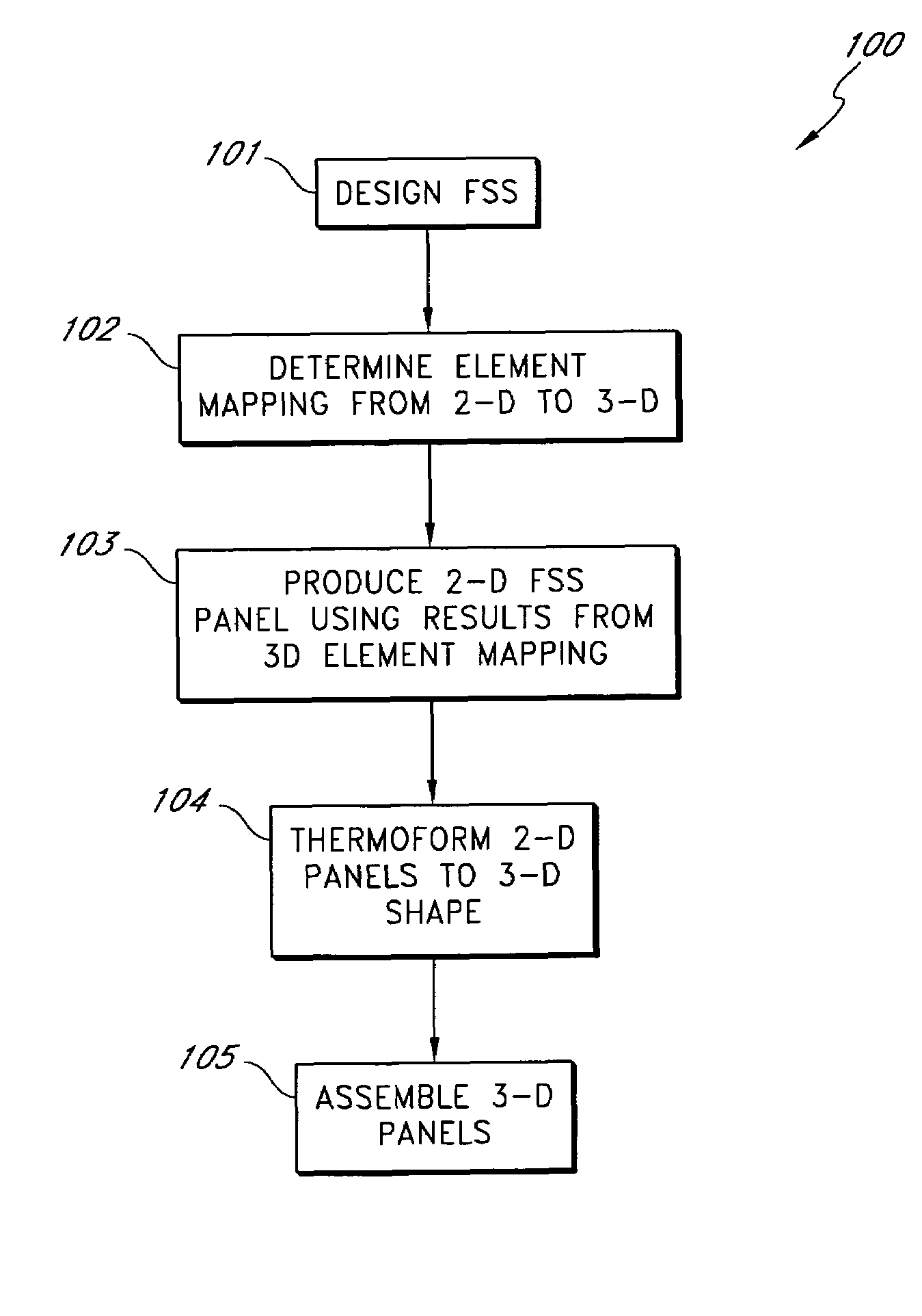
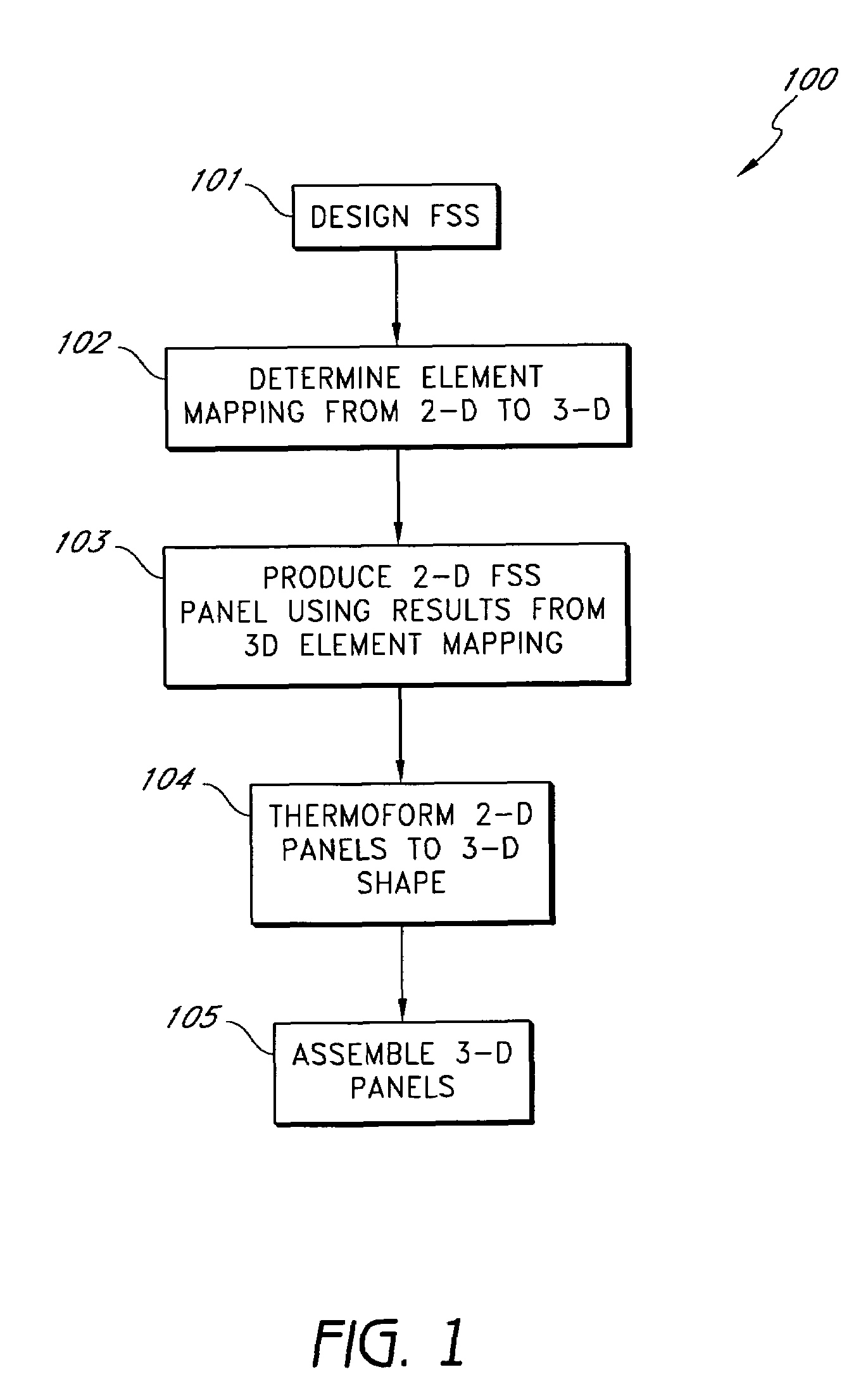
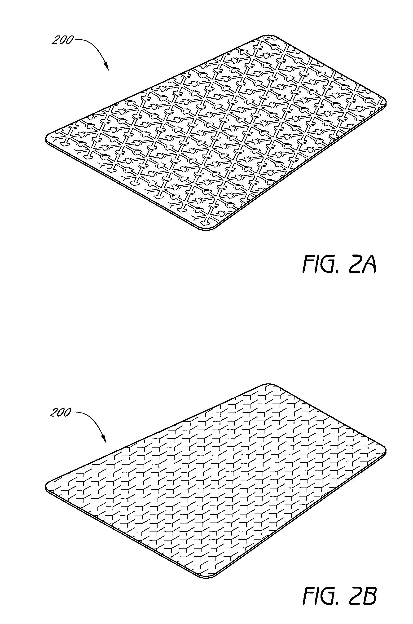
[0015]FIG. 1 is a flowchart showing a 3-D FSS design and fabrication process 100. In a first process block 101, a FSS structure is designed. Typically, the design programs and techniques used in the process block 101 assume the FSS is flat or that the radius of curvature of the FSS is relatively large with respect to the wavelength of a desired operational band of the FSS. The resulting design for a typical radome or other FSS structure includes the number of layers, the dielectric constant of the materials used in and around the FSS layers, the shape of the FSS elements in each layer and the spacing between FSS elements in each layer. Although not required, it is typical that the FSS elements are uniformly spaced on each FSS layer. Even when uniform spacing is not used, the spacing between elements affects the operational properties of the FSS and it is generally desirable to be able to control the element spacing during construction of the FSS layers. If the final FSS layers are t...


PUM


Abstract

A three-dimensional FSS fabrication system is described. FSS elements are pre-mapped in two-dimensional form and constructed on a flat FSS panel that is then formed into a desired three-dimensional shape. The 2-D flat surface of the designed FSS is mapped into a desired three-dimensional curvature so that when formed from 2-D into the 3-D shape, the FSS elements are moved into a desired position and / or orientation. In one embodiment, the mapping from 2-D to 3-D is performed using the elastic properties of a desired substrate material. In one embodiment, one or more flat FSS panels are constructed on a formable or thermo-formable substrate. In one embodiment, the substrate includes a thermoplastic. In one embodiment, the substrate includes a thermoplastic material with fiber reinforcement. The FSS elements can be created by printing, deposition, photo-etching, etc. The flat FSS layers are thermoformed or chemically formed over a tool having the desired shape. In one embodiment, the FSS layers are formed to the shape of the tool by using vacuum techniques. In one embodiment, the FSS layers are formed to the shape of the tool by supporting the FSS layer between male and female tools.

Description

BACKGROUND OF THE INVENTION[0001]1. Field of the Invention[0002]The invention relates to methods for thermoforming Frequency Selective Surfaces (FSS) for antennas, radomes and the like.[0003]2. Description of the Related Art[0004]Frequency selective surfaces (FSS) are useful in many radio-frequency and optical applications. Such applications include antennas, radomes, canopies, and other aircraft structures and the receiving surfaces of satellite dishes. A surface may be made frequency selective by forming a pattern on the surface, for example, by applying a patterned metal layer to the surface. The accuracy of the frequency selectivity of the surface depends on the precision of the pattern formed on the surface. Curvature in the surface complicates the pattern and makes fabrication difficult. Currently, there is no known method for patterning curved surfaces to achieve precise frequency selectivity in a cost effective manner.SUMMARY[0005]These and other problems are solved by using...

Claims


Application Information

Patent Timeline
Patent Type & Authority Patents(United States)
IPC IPC(8): H01Q15/02
CPCH01Q15/0046H01Q1/085H01Q15/02
Inventor WILLIAMS, VICTOR G.MACFARLAND, ANDREW B.SALADIN, ETHAN C.MARCUM, JAY C.
Owner ORBITAL ATK INC
Learn More