Galvanically isolated signal conditioning system

a signal conditioning and galvanic isolation technology, applied in the direction of fixed capacitor details, fixed capacitors, instruments, etc., can solve the problems of large physical size and weight, large area consumed by printed circuit boards or printed wire boards, high cost, etc., and achieve the effect of small size and weight, small compact package, and low cos

Active Publication Date: 2006-07-13
ANALOG DEVICES INC
View PDF32 Cites 35 Cited by
  • Summary
  • Abstract
  • Description
  • Claims
  • Application Information

AI Technical Summary

Benefits of technology

[0011] It is a further object of this invention to provide such an improved galvanically isolated signal conditioning system which is small in size and weight, does not physically scale up with measured current, is lower cost, accurate and can measure AC and DC currents and voltages and does not require special power supplies.
[0012] It is a further object of this invention to provide such an improved galvanically isolated signal conditioning system in which the signal conditioning circuit and MEMS switching device can be implemented on small stacked or adjacent integrated circuit chips or on one and the same integrated circuit chip made by inexpensive high volume semiconductor processes resulting in a small compact package.
[0013] The invention results from the realization that a truly galvanically isolated signal conditioning system which is small, compact, less expensive, and accurate can be effected by using a MEMS switching device to selectively switch a flying capacitor between a higher voltage input and lower voltage signal conditioning circuit where both the MEMS switching device and the signal conditioning circuit are on integrated circuit chips either separate but adjacent or stacked chips or on one and the same chip.

Problems solved by technology

This approach can result in a solution which consumes a relatively large area of printed circuit board or printed wire board due to the mechanical relays.
The disadvantages of the current transformer approach include large physical size and weight, especially as measured current increases, high cost, inability to measure dc currents and voltages and limited accuracy.
Disadvantages of the Hall effect approach include low accuracy with an open loop sensor, the need for an isolated power supply to power the isolated side, offsets due to the Hall effect elements and high cost and large physical size for closed loop sensors.
Disadvantages of this approach include large physical size, high cost, the need for an isolated power supply to power the isolated side and poor accuracy.
Disadvantages of this approach include the need for an isolated power supply to power the isolated side, the need to filter the data stream to extract the sensed signal, high frequency clock and data signals that potentially are a cause of radio frequency interference (RFI), front-end offset drift and gain drift issues over time and temperature, and a relatively expensive low-drift sense resistor.

Method used


Image

  • Galvanically isolated signal conditioning system
  • Galvanically isolated signal conditioning system
  • Galvanically isolated signal conditioning system

Examples


Embodiment Construction

[0028] Aside from the preferred embodiment or embodiments disclosed below, this invention is capable of other embodiments and of being practiced or being carried out in various ways. Thus, it is to be understood that the invention is not limited in its application to the details of construction and the arrangements of components set forth in the following description or illustrated in the drawings. If only one embodiment is described herein, the claims hereof are not to be limited to that embodiment. Moreover, the claims hereof are not to be read restrictively unless there is clear and convincing evidence manifesting a certain exclusion, restriction, or disclaimer.

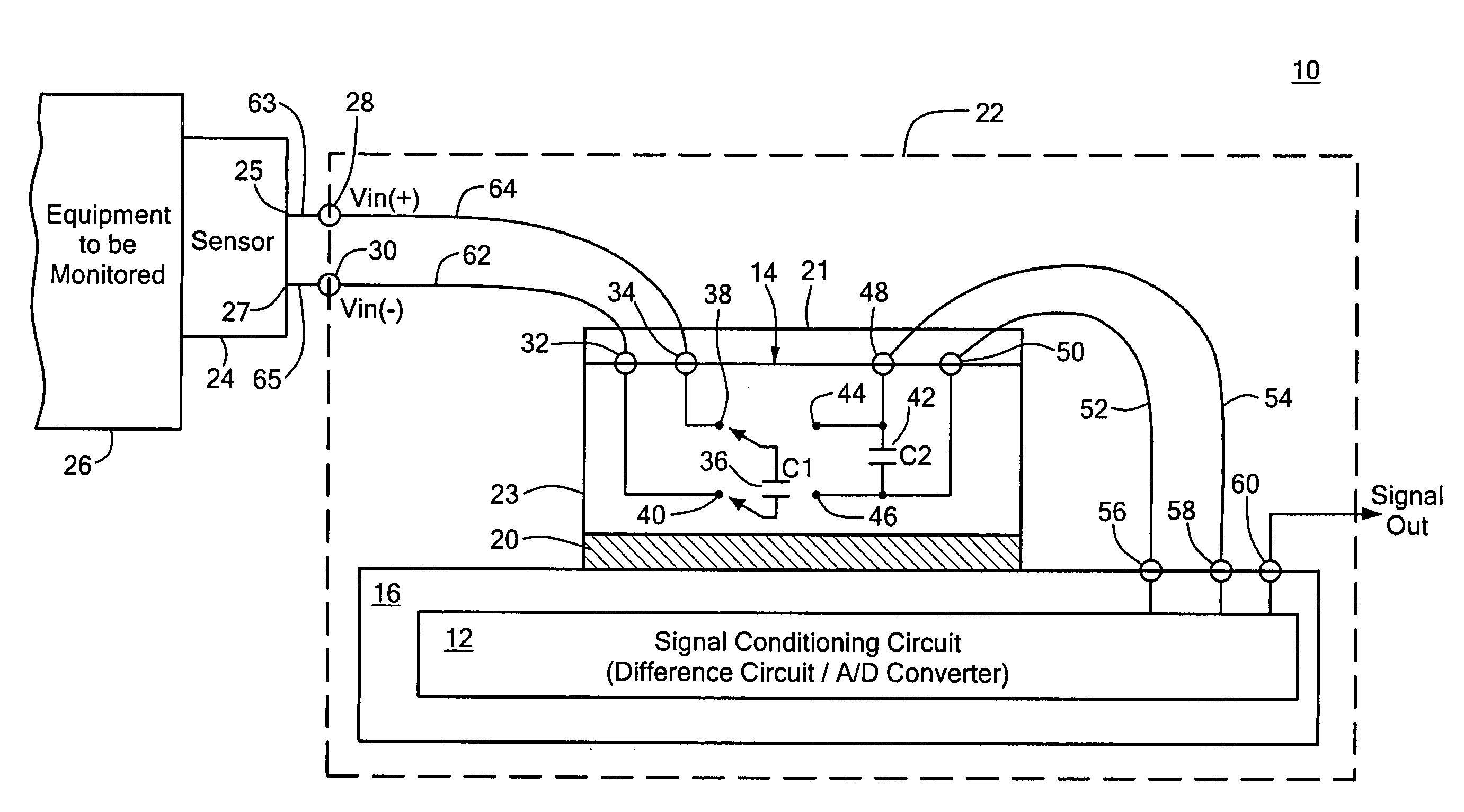
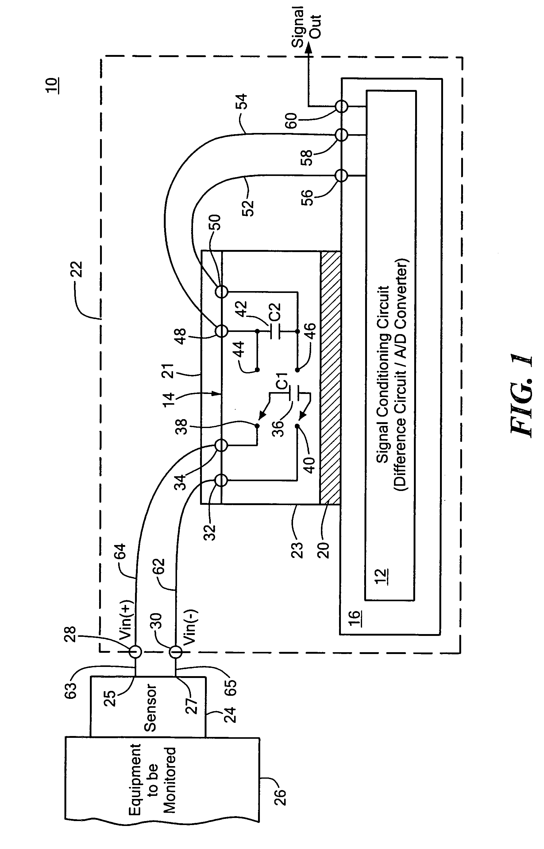
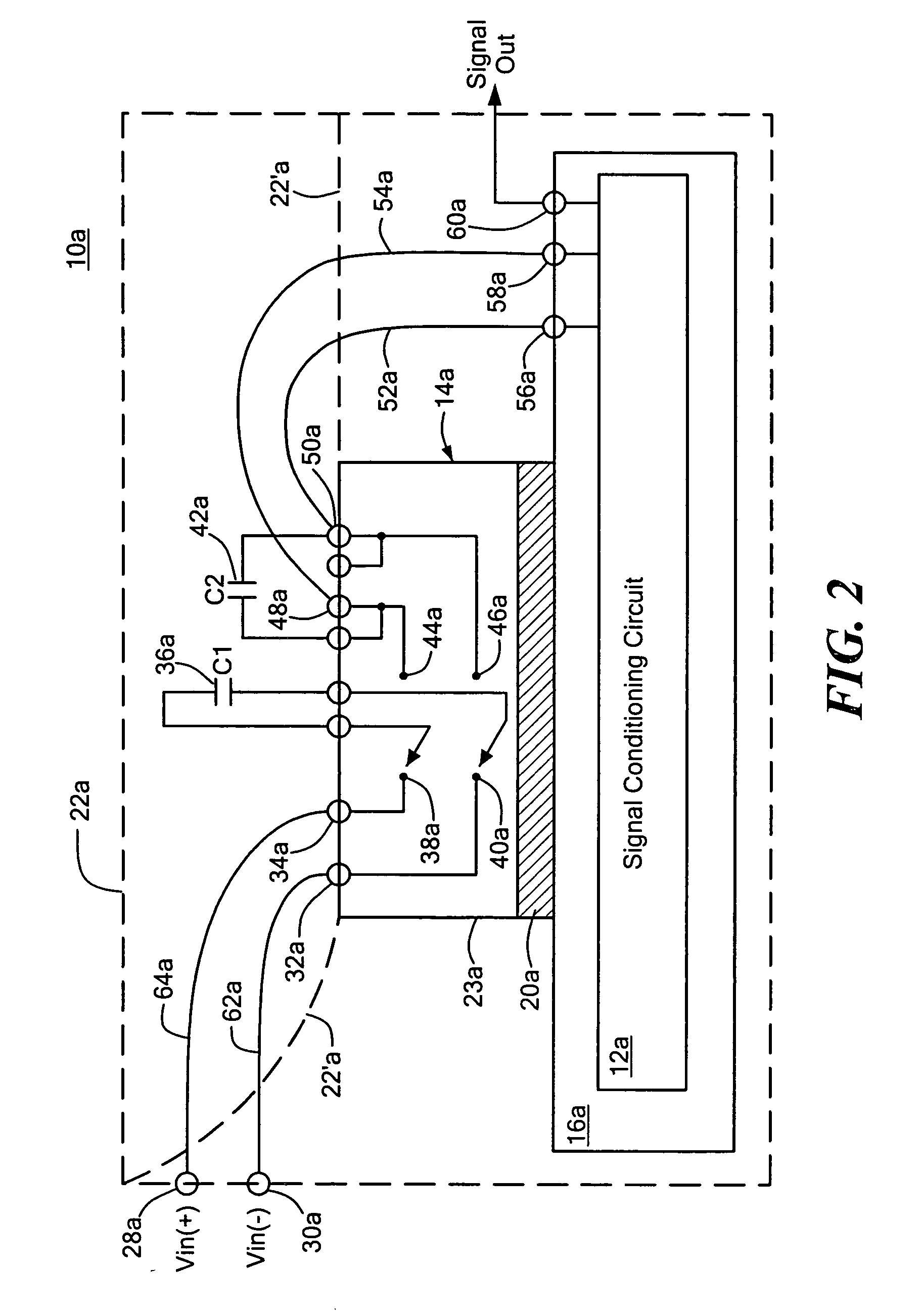
[0029] The improved galvanically isolated signal conditioning system of this invention uses a combination of manufacturing technologies to achieve its advantages. By utilizing switches manufactured using a MEMS-based process, together with a signal conditioning circuit such as an analog to digital converter or a differenc...


PUM


Abstract

A galvanically isolated signal conditioning system includes a signal conditioning circuit on an integrated circuit chip; a flying capacitor; and a galvanically isolating MEMS switching device on an integrated circuit chip for selectively switching the flying capacitor from across a pair of input terminals in one state to across the input terminals of the signal conditioning circuit in another state.

Description

FIELD OF THE INVENTION [0001] This invention relates to a galvanically isolated signal conditioning system, and more particularly to such a galvanically isolated signal conditioning system employing a MEMS switched flying capacitor. BACKGROUND OF THE INVENTION [0002] Signal conditioning circuits such as difference amplifiers are often employed in data acquisition applications where isolation is desirable between the potentially much higher voltage of the monitored equipment and the lower voltage of the signal conditioning circuit, for example. [0003] A difference amplifier amplifies the potential difference between its two inputs. Differential signals can be found in many applications, from simple ohmic drops across a sense resistor in a current sensing application to the output of a standard resistive bridge or load cell. Normally the sensed differential voltage is fairly small; usually of the order of microvolts to perhaps hundreds of millivolts. [0004] Usually associated with eve...

Claims


Application Information

Patent Timeline
Patent Type & Authority Applications(United States)
IPC IPC(8): G02B6/26
CPCG01D5/24G11C27/024H01H2059/0054
Inventor WYNNE, JOHNHYNES, EAMON
Owner ANALOG DEVICES INC
Why Eureka
Try Eureka